background image

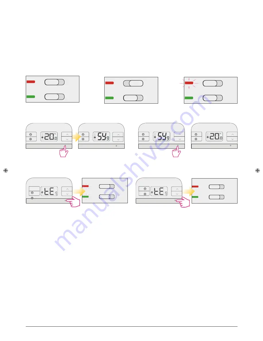
Test Pairing Function

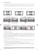
Make sure your devices are wired and the thermostat has batteries inserted. Switch receiver to ON. If you are 
using the RT310RF pack, the pairing between the thermostat and the receiver is already done. If you bought 
the RT310TX and RXRT510 separately then pair as follows. Please make sure that the Receiver is set on Auto.

ON

AUTO

OFF

MANUAL

ON

AUTO

OFF

MANUAL

TESTING/PAIRING

TESTING/PAIRING

Test the pairing process

TESTING/PAIRING

TESTING/PAIRING

TESTING/PAIRING

3 Sec

Wait 9 minutes for the timeout 

process to be complete.

Begin the pairing process

End the pairing process

TESTING/PAIRING

3 Sec

Testing the RF transmissions

It is important to site both the Receiver and thermostat in locations where the RF signal cannot be interrupted. 
The receiving range between the thermostat and Receiver is approximately 30 metres indoors, however many factors can 
affect the RF transmission and shorten the operating distance, e.g. shielding by thick walls, foil back plasterboard, metal 
objects such as filing cabinets, general RF interference, and so on. The range is generally large enough for most household 
applications, but it is advisable to test the RF transmission from the intended thermostat location to the Receiver location 
before fixing the thermostat to the wall.
To check the RF reception, follow the following steps:
1.  Press the UP button on the thermostat until the set point temperature is higher than room temperature by a few 

degrees.

2.  Wait for a few seconds. The Heat on (heat call) indicator should appear on the bottom left of the LCD on the thermostat.
3.  Check the green LED on the receiver unit - it should be lit.
4.  Press the DOWN button to adjust the set point temperature to be lower than room temperature.
5.  Wait for a few seconds, and the Heat on (heat call) indicator should disappear and the green LED should switch off.
6.  If at step 3 the green LED is not illuminated, press the TEST/PAIRING button on the thermostat and try to place the 

thermostat closer to the Receiver.

7.  Repeat steps 1 to 5.

Note: Before beginning the process, switch the receiver On/Off and then On again to reset it (On/Off/On).

ON

AUTO

OFF

MANUAL

ON

AUTO

OFF

MANUAL

ON

AUTO

OFF

MANUAL

08   RT310RF Installation Manual

Summary of Contents for RT310RF

Page 1: ...Installation Manual Model RT310RF...

Page 2: ...ormation 3 Box Content 3 Introduction 4 Features 5 Installation 5 Button functions and keys 7 Installer mode 9 Operations 10 Other functions 12 Factory reset 13 Technical info 13 Warranty 14 02 RT310R...

Page 3: ...ational regulations For indoor use only Keep your device completely dry ThisproductmustbeinstalledbyacompetentpersonandinaccordancewithalltheEUandnationalregulations Always isolate the AC Mains supply...

Page 4: ...o its job The best way to do this is to set the room thermostat to a low temperature say 18 C and then turn it up by one degree each day until you are comfortable with the temperature You won t have t...

Page 5: ...hes are found on the rear of your thermostat and can be used to change the span temperature accuracy of your thermostat from the default 0 5 C to 0 25 C This may cause your boiler to operate more freq...

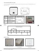
Page 6: ...Terminal Mains Live 230VAC Mains Neutral Wiring Fit the front housing Press lightly Fix the backplate to the wall Align the front housing at the top edge NO COM L N L N Electrical diagram COM NO L N...

Page 7: ...will turn on the boiler OFF When in Manual Mode OFF will turn off the boiler Red Led Receiver On paired Green Led Command from thermostat received There are few user controls for the RT310RF making th...

Page 8: ...uch as filing cabinets general RF interference and so on The range is generally large enough for most household applications but it is advisable to test the RF transmission from the intended thermosta...

Page 9: ...for 10 seconds or press See the table below dxx Function Parameter Description Default value d01 Temperature display increments 0 1 C or 0 5 C Select the temperature display increments 0 5 C d02 Tempe...

Page 10: ...om Temperature 22 0 C to be renewed within 5 seconds Setpoint Temperature 20 0 C C indicator On Frost Protection indicator Off Heat indicator Off Low Battery Warning indicator Off to be renewed within...

Page 11: ...ss FROST button to activate Frost Protection The Setpoint temperature is automatically set to frost setpoint to prevent freezing If the room temperature is lower than the frost setpoint frost protecti...

Page 12: ...s to to do so without losing your settings Sleep Mode Press and hold and for 3 seconds simultaneously to enter the Sleep mode All the functions will be paused to save battery power While in sleep mode...

Page 13: ...nt Temperature Range 5 C to 17 C Thermostat Power Source 2 AA sized Alkaline Batteries for a minimum of 12 months operation Receiver Power Source 230Vac 50Hz Switch Rating Switching Voltage 230V 50Hz...

Page 14: ...ification for a period of two years from the date of installation SALUS Controls sole liability for breach of this warranty will be at its option to repair or replace the defective product Customer Na...

Page 15: ...tech salus tech com www salus controls com SALUS Controls is a member of the Computime Group Maintaining a policy of continuous product development SALUS Controls plc reserves the right to change spec...

Reviews: