RT500ROF INSTRUCTION MANUAL
15
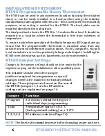
To adjust the RF address code of the RT500,
remove one or more of the jumper caps
located on the back of the unit (labelled
1,2,3,4 and 5 shown in the picture
opposite) so that the jumper settings match
the settings made on the receiver:
For example, if the DIP switches
on the Receiver were set as follows:
1 - ON
2 - OFF
3 - OFF
4 - OFF
5 - ON
Then you would need to remove jumper caps 2, 3 and 4 on the
RT500 to make sure that they are both set with the same RF address
code. Please make sure that you keep any of the jumper caps you
remove in a safe place, in case you later need to change the RF
address setting again.
Turning on the Receiver at this point, the red LED will flash for 12
minutes to indicate the Receiver is in sync mode. During the pairing
process, the Receiver will go into NORMAL mode if the pairing
process is not completed within 12 minutes. After successfully
completing the pairing process, the red LED of Receiver will stop
flashing, then you can press the button of OTO to control the receiver
relay.
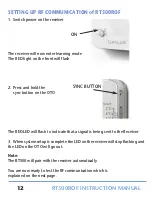
To pair the One Touch Energy Override Control with the Receiver,
gently press and hold the SYNC button for a few seconds with a sharp
object (such as the end of a paper clip). The front LED will flash every
few seconds and a RF address code will be generated and saved. The
OTO unit will continuously transmit the RF signal for 5 minutes to
the Receiver.
If the Receiver loses the signal from the OTO for more than 1 hour,
the red LED will flash, and the setback temperature will be cancelled.
RT500ROF Manual Ver039.qxp_89 21/10/2015 12:34 Page 15


