background image

RT500ROF INSTRUCTION MANUAL

28

ENERGY TIP

One way to set and use your room thermostat is to find the lowest
temperature setting that you are comfortable with, and then leave it set at
this temperature. You can do this by setting the room thermostat to a low
temperature, (for example 17 °C) and then increasing the setting by one
degree each day until you are comfortable with the room temperature - you
won’t have to adjust the thermostat further, as adjustment above this setting
will waste energy - a 1 °C increase in temperature is equal to 3% of your
heating costs. Additionally use the OTO when leaving the property.

MAINTENANCE

The RT500ROF requires no special maintenance. Periodically, the outer
casing of all components can be wiped clean using a dry cloth (please DO
NOT use solvents, polishes, detergents or abrasive cleaners, as these can
damage the thermostat).

There are no user serviceable parts within the units; any servicing or repairs
should only be carried out by SALUS Controls or their appointed agents.

Should the RT500 programmable thermostat fail to function correctly,
check:

The RT500 or One Touch Override batteries are the correct type, 
fitted correctly and are not exhausted - fit new batteries if in doubt.

Heating system is switched on.

The RT500 Receiver is switched on.

If the RT500 is still not functioning correctly, press the Reset Button.

WARRANTY

SALUS Controls warrants that this product will be free from any defect in
materials or workmanship, and shall perform in accordance with its
specification, for a period of two years from the date of installation.
SALUS Controls sole liability for breach of this warranty will be (at its option)
to repair or replace the defective product. 

RT500ROF Manual Ver039.qxp_89  21/10/2015  12:34  Page 28

Summary of Contents for RT500ROF

Page 1: ...Instruction Manual Model No RT500ROF Programmable RF Room Thermostat with One Touch Energy Saving Override Control ...

Page 2: ...be followed along with any other statutory obligations This accessory must be fitted by a competent person and installation must comply with the guidance provided in the current editions of BS7671 IEE Wiring Regulations and Part P of the Building Regulations Failure to comply with the requirements of these publications could lead to prosecution Always isolate the AC Mains supply before opening or ...

Page 3: ...urning a programmable room thermostat to a lower setting will result in the room being controlled at a lower temperature and saves energy The way to set and use your programmable room thermostat is to find the lowest temperature settings that you are comfortable with at the different times you have chosen and then leave it alone to do its job The best way to do this is to set low temperatures firs...

Page 4: ...programme on the programmable room thermostat can be temporarily overridden using the remote override control The One Touch Override OTO is normally mounted at the main exit of the property and is pressed on entry or exit When activated the OTO will override the programmed temperature on the RT500 Programmable room thermostat YOUR RT500ROF INCLUDES THE FOLLOWING RT500 Programmable Room Thermostat ...

Page 5: ...vated when leaving your property or when you just want to override the programme on the RT500 programmable room thermostat RT500ROF Features One Touch Energy Saver Override Control RF Volt free switching option 5 2 or 7 day programming flexibility Built in start up programming for quick installation Frost protection Large easy to read display with blue backlight Burner on symbol Easy to use progra...

Page 6: ...ounted away from any possible sources of interference such as radios TV sets computers etc and is not mounted on or in close proximity to large metal objects Installing the RT500 in enclosed areas such as basements is not recommended RT500 Jumper Settings Changes to the jumper settings should only be made by the engineer carrying out the installation or other qualified person The installer should ...

Page 7: ...riately 13A max The Receiver should be mounted in a location where it will not come into contact with water moisture or condensation The On Off switch is accessible from the front face of the Receiver as shown in this picture On the front cover of the Receiver you will see that there is the On Off switch and two Light Emitting Diodes LEDs The switch allows you to turn off the Receiver if necessary...

Page 8: ... WIRING INSTALLATIONS a 230V AC Installation Notes Receiver should have a permanent 230V AC fused Mains supply Confirm that the Boiler has an external thermostat loop and is configured for 230V switching If the boiler has two terminals for the thermostat remove the link from the boiler As the Receiver is compatible with 0v 240v boiler the wiring is the same for all boilers with a 2 wire connection...

Page 9: ...Receiver unit should have a permanent 230V AC main supply Confirm that the Boiler has an external thermostat loop and is NOT configured for 230V switching If the boiler has two terminals for the thermostat remove the link from the boiler Boiler Mains supply ...

Page 10: ...here inside the property for convenience We suggest mounting the unit at the main entry exit of the property 1 To begin installation remove the front cover by sliding it up from the back plate 2 Mark and drill two holes at points A Fix the OTO back plate to the wall using the screws and anchors provided A A ...

Page 11: ...F INSTRUCTION MANUAL 11 3 Insert the two AAA batteries supplied into the bottom rear of the front cover 4 Position the front cover above the back plate and slide down until the cover is in line with back plate ...

Page 12: ...Press and hold the sync button on the OTO The RED LED will flash to indicate that a signal is being sent to the Receiver 3 When system setup is complete the LED on the receiver will stop flashing and the LED on the OTO will go out Note The RT500 will pair with the receiver automatically You are now ready to test the RF communication which is explained on the next page SYNC BUTTON ON ...

Page 13: ... temperature 2 Wait for a few seconds The flame indicator heat call should appear on the bottom left of the LCD on the RT500 3 Check the green LED on the receiver unit it should be lit 4 Select setback of OTO press the big button to transmit the setback signal to the Receiver The green LED on the Receiver should be turned off This can test the RF range between the OTO and the Receiver 5 Press the ...

Page 14: ...s from the RT500 and One Touch Override module before attempting any adjustment of the RF Address Code switches and jumpers If you are not sure how to carry out this operation correctly consult either with a qualified electrician or heating engineer or contact the SALUS Controls Technical Helpline for advice on how to continue To adjust the RF address code of the Receiver simply push up one or mor...

Page 15: ...at this point the red LED will flash for 12 minutes to indicate the Receiver is in sync mode During the pairing process the Receiver will go into NORMAL mode if the pairing process is not completed within 12 minutes After successfully completing the pairing process the red LED of Receiver will stop flashing then you can press the button of OTO to control the receiver relay To pair the One Touch En...

Page 16: ...ndicator Off Heat indicator Off Low Battery Warning indicator Off updated within 5 seconds Output Relay Off After Power on the thermostat will operate in Normal mode Normal mode is when the thermostat is displaying the room temperature The set point temperature is reset to the default setting The room temperature display is updated within 5 seconds The control process starts The programme number i...

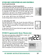
Page 17: ...ouch Override 1 Selecting the set back temperature On the Side of the One Touch Override OTO you will see a vertical slide switch The slide switch allows you to select an override temperature that will operate when the OTO is activated If you select 2ºC 4ºC or 6ºC then the active temperature selected on the RT500 programmable room thermostat will be reduced by either 2ºC 4ºC or 6ºC If you select A...

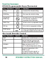
Page 18: ...is used or manual override setpoint or programme setting of that day Function Summary RT500 Programmable Room Thermostat Key Operation Symbol Functions UP key Increases the selected setting DOWN key Decreases the selected setting BACKLIGHT Manually turns on the LCD backlight FROST key for 5 seconds or activates deactivates Frost Protection SELECT key Selects a clock or programme setting SET key Se...

Page 19: ...is the currently selected item and is ready to be adjusted Press the UP or DOWN keys to increase or decrease the hour setting the selected item will stop flashing while a key is pressed and will resume flashing when you release the key Press the SELECT key to select the minutes section of the time Set the minutes in the same way as the hour by using the UP and DOWN keys Press SELECT again to selec...

Page 20: ...efault programming mode 5 2 or 7 day is made by changing the jumper setting on the rear of the RT500 as previously described within the Installation section of this manual 5 2 DAY MODE 5 2 day mode is the default programming mode for the RT500 With this mode selected five different sets of time and set point temperatures can be set for Weekdays or Weekends To review or change a programme press the...

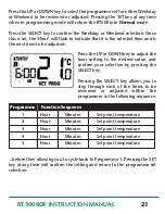
Page 21: ... UP or DOWN key to adjust the hour setting to the desired value and confirm your selection by pressing the SELECT key Pressing the SELECT key allows you to step through each of the items to be reviewed or adjusted within the programmes in the following sequence Programme Function Sequence 1 Hour Minutes Set point temperature 2 Hour Minutes Set point temperature 3 Hour Minutes Set point temperature...

Page 22: ...rogramme Setting mode The LCD display will display programme number 1 and SET PROG with all other indicators cleared The weekdays will be flashing to indicate they are the selected item and are ready to be adjusted Press the UP or DOWN key to change the display to indicate the single day you want to programme Pressing the SET key at any time when in programming mode will return the RT500 into Norm...

Page 23: ... confirm the setting and return to the programme set selection Each programme for all the other days of the week is set in exactly the same way just repeat the steps shown above after entering programming mode and selecting the day you want to programme Regardless of which programming mode the RT500 is set for 5 2 or 7 day not pressing any keys for 15 seconds will automatically save any programmin...

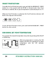
Page 24: ...to 5 C Whenever Frost Protection is activated the Frost Protection indicator will flash in the sequence shown below To turn off Frost Protection mode press and hold the BACKLIGHT FROST button for a few seconds REVIEWING SET POINT TEMPERATURE You can view the set point temperature at any time by pressing either the UP or DOWN key When any programme is running the LCD display will show the programme...

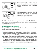
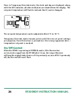
Page 25: ... TEMPORARY OVERRIDE It is possible to temporarily override the current set temperature of the RT500 There are two ways to do this While reviewing set point temperature Pressing the UP or DOWN key while reviewing the set point temperature will increase or decrease the set point temperature in 0 5 C steps In Normal mode press and hold either the UP or DOWN key to display the set point temperature Af...

Page 26: ...be adjusted within 5 C to 35 C Temporary Override mode remains active until the new set point settings are adjusted Frost Protection is activated or the next programme time temperature set point is reached On Off Control When the RT500 is operating in NORMAL mode if the Receiver has not received a signal from the RT500 after 1 hour the relay of Receiver will keep the original status turn on if it ...

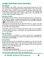
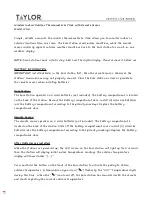
Page 27: ...hough the programmable thermostat will continue to operate normally at this stage you should replace the batteries as soon as possible to prevent any possible operating problems If the LED on the One Touch Override front panel is dim or does not light it means the batteries are low or discharged you should replace the batteries as soon as possible Reset Button The Reset Button is provided as a way...

Page 28: ...ry cloth please DO NOT use solvents polishes detergents or abrasive cleaners as these can damage the thermostat There are no user serviceable parts within the units any servicing or repairs should only be carried out by SALUS Controls or their appointed agents Should the RT500 programmable thermostat fail to function correctly check The RT500 or One Touch Override batteries are the correct type fi...

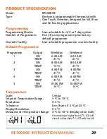
Page 29: ...programme override facility Default Programmes Programme Output Weekday Weekend 1 ON 6 00 AM 6 00 AM TEMP 21 ºC 21 ºC 2 ON 8 00 AM 8 00 AM TEMP 14 ºC 21 ºC 3 ON 4 00 PM 4 00 PM TEMP 21 ºC 21 ºC 4 ON 6 00 PM 6 00 PM TEMP 21 ºC 21 ºC 5 ON 10 00 PM 10 00 PM TEMP 14 ºC 14 ºC Temperature Scale Celsius Setpoint Temperature Range 5 ºC to 35 ºC Resolution 0 5 ºC Tolerance Less than 0 5 ºC at 25 ºC Display...

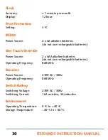
Page 30: ...rgeable batteries One Touch Override Power Source 2 x AAA alkaline batteries do not use rechargeable batteries Operating Frequency 868 MHz Receiver Power Source 230V AC 50Hz Operating Frequency 868 MHz Switch Rating Switching Voltage 230V AC 50Hz Switching Current 16A resistive 5A inductive Environment Operating Temperature 0 ºC to 40 ºC Storage Temperature 20 ºC to 60 ºC ...

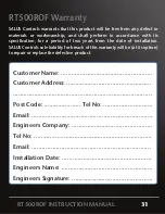
Page 31: ... period of two years from the date of installation SALUS Controls sole liability for breach of this warranty will be at its option to repair or replace the defective product RT500ROF Warranty Customer Name Customer Address Post Code Tel No Email Engineers Company Tel No Email Installation Date Engineers Name Engineers Signature RT500ROF INSTRUCTION MANUAL 31 ...

Page 32: ...alus tech com Tel 01226 323961 Email tech salus tech com Tel 01226 323961 Sales Technical SALUS Controls plc SALUS House Dodworth Business Park South Whinby Road Dodworth Barnsley S75 3SP salus tech DOC 00003 Rev 1 ...

Reviews: