background image

i

Regulatory Statements 

FCC

This device complies with Part 15 of the FCC Rules. Operation is subject to the following two conditions: (1) this 

device may not cause harmful interference, and (2) this device must accept any interference received, including 

interference that may cause undesired operation. 
Changes or modifications to this unit not expressly approved by the party responsible for compliance could void 

the user’s authority to operate the equipment. 
NOTE: This equipment has been tested and found to comply with the limits for a Class B digital device, pursuant to 

Part 15 of the FCC Rules. These limits are designed to provide reasonable protection against harmful interference 

in a residential installation. This equipment generates, uses and can radiate radio frequency energy, and if not 

installed and used in accordance with the instructions, may cause harmful interference to radio communications. 

However, there is no guarantee that interference will not occur in a particular installation. If this equipment does 

cause harmful interference to radio or television reception, which can be determined by turning the equipment off 

and on, the user is encouraged to try to correct the interference by one or more of the following measures: 


Reorient or relocate the receiving antenna.


Increase the separation between the equipment and receiver. 


Connect the equipment into an outlet on a circuit different from that to which the receiver is connected. 


Consult the dealer or an experienced radio/ TV technician for help.

FCC AND INDUSTRY CANADA

RF Radiation Exposure statement: This equipment complies with FCC and Industry Canada RF radiation exposure 

limits set forth for an uncontrolled environment. This equipment should be installed and operated with a minimum 

distance of 20 centimeters between the antenna and all persons. 
Cet appareil est conforme aux limites d’exposition au rayonnement FR du FCC et d’Industrie Canada pour un 

environnement non contrôlé. Cet appareil devrait être installé et devrait fonctionner de sorte qu’il se trouve à une 

distance d’au moins 20 cm entre l’antenne et toute personne.

INDUSTRY CANADA

This device complies with Industry Canada license-exempt RSS standard(s). Operation is subject to the following 

two conditions: (1) this device may not cause interference, and (2) this device must accept any interference, 

including interference that may cause undesired operation of the device. 
Le présent appareil est conforme aux CNR d’Industrie Canada applicables aux appareils radio exempts de licence. 

L’exploitation est autorisée aux deux conditions suivantes : (1) l’appareil ne doit pas produire de brouillage, et (2) 

l’utilisateur de l’appareil doit accepter tout brouillage radioélectrique subi, même si le brouillage est susceptible 

d’en compromettre le fonctionnement.

Summary of Contents for ST921WF

Page 1: ...ST921WF SOLO 2H 1C Wi Fi Thermostat Installation Manual For other language versions please visit www salusinc com...

Page 2: ...e the separation between the equipment and receiver Connect the equipment into an outlet on a circuit different from that to which the receiver is connected Consult the dealer or an experienced radio...

Page 3: ...tat uses a 24 VAC power source DO NOT expose the unit to voltage fluctuations of more than 10 DO NOT cover any of the vents on the thermostat DO NOT allow the unit to get wet This device serves as a t...

Page 4: ...rns information important to reliable operation of the controls or helpful installation setup information Safety Indicates a condition which may cause severe personal injury death or major property da...

Page 5: ...ff Power to HVAC System 2 Determine Wiring Configuration 3 Remove Old Thermostat 5 Install Mounting Plate 6 Attach Wiring 7 Attach Display to Mounting Plate 8 Turn on Power to HVAC System 9 DEVICE BOO...

Page 6: ...1 In The Box ST921WF Thermostat with Mounting Plate Wall Plate if required Mounting Screws Anchors Installation Manual...

Page 7: ...s to install the ST921WF Thermostat 1 Phillips or flathead screwdriver Power drill with 3 16 bit if new mounting holes are required Smartphone camera to photograph wiring for reference optional Screwd...

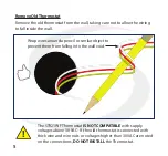
Page 8: ...and replicating the wiring of the existing thermostat is desired on the ST921WF the following applies Remove the old thermostat to expose the wiring terminals Photograph the wiring for reference or u...

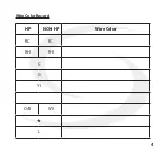
Page 9: ...4 Wire Color Record HP NON HP Wire Color RC RC RH RH C G Y1 O B W1 L...

Page 10: ...The ST921WF Thermostat IS NOT COMPATIBLE with supply voltages above 30 VAC If the old thermostat is connected with thick wire and wire nuts or voltages higher than 30 VAC are noted on the connections...

Page 11: ...nd screws to attach the Mounting Plate to the wall making sure the wires run through the center opening To cover paint or screw holes on the wall behind the thermostat insert the Wall Plate between th...

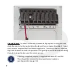
Page 12: ...bel Insert each wire as required for the desired appliance Once each wire is inserted flip the tab down to lock it in position Pull gently on each wire after locking the tab is closed to be sure the w...

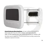
Page 13: ...e back of the thermostat with the posts on the wall plate and snap it into place Make sure the connector pins are not bent and wires do not interfere with the thermostat engagement The thermostat must...

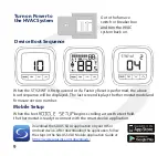
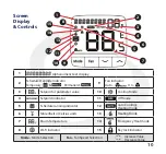
Page 14: ...last screen displays the thermostat model and firmware version number Mobile Setup When the text begins scrolling across the text field the thermostat is ready to connect with the smart device applic...

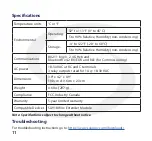
Page 15: ...Setpoint indicator 11 Off Mode 5 Schedule running indicator 12 Auto Cooling Heating mode 6 Fahrenheit or Celsius units 13 Heating Mode 7 Room Temperature 14 Emergency Heat mode 8 Wi Fi indicator 15 K...

Page 16: ...tooth v4 2 BR EDR and BLE for Commissioning AC power 18 30 VAC at RC and C terminals 3 relay outputs rated for 1A 18 30 VAC Dimensions 3 9 x 4 2 x 0 9 10 0cm x10 6cm x 2 3cm Weight 0 6 lbs 297 g Compl...

Page 17: ...orized Salus representative ii which has not been maintained in accordance with any handling or operating instructions supplied by Salus or iii which has been subjectedtounusualphysicalorelectricalstr...

Page 18: ...has determined that the Product is defective and the Customer is eligible for a replacement or Contact Salus Service at support salusinc com to determine whether the device qualifies for a replacement...

Page 19: ...rminal Non Heat Pump Heat Pump RC 24 VAC Power Cool RH 24 VAC Power Heat C 24 VAC Common Use SA918 Wire Extender if C wire is not available G Fan Y1 Cooling Compressor Not Used Not Used W1 OB Heating...

Page 20: ...15 Conventional Single Transformer Heat and Cool System...

Page 21: ...16 Conventional Two Transformer Heat and Cool System...

Page 22: ...17 Single Transformer Heat Pump System...

Page 23: ...18 This page intentionally left blank...

Page 24: ...SMC IM ST921WF 202007v1 Copyright SALUS North America Inc 2020 SALUS NA Inc 888 387 2587 sales salusinc com www salusinc com...

Reviews: