background image

21

6. Installer parameters

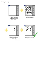
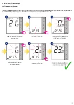
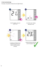
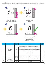
To enter installer parameters please follow steps below. Please refer to parameters table description before any changes. Use 

 or 

 buttons to move 

up or down between all parameters. Every change/selection confirm by    button:

dXX

Function

Parameter 

Values

Description

 Default 

Values

d01

Control method

temperature

This parameter defines the algorithm of the room temperature control.

0

0

PWM (Pulse-width modulation) algorithm ensures reduction of overdrive 

states and economic operation of the system. It is an advanced algorithm 

designed to precisely maintain room temperature.

1

SPAN ± 0.5°C (± 1°F)

2

SPAN ± 1°C (± 1.5°F)

d02

Offset temperature

-3.0°C to 

+ 3.0°C

Offset room temperature measuring is a function which allows user to 

recalibrate internal thermostat’s temperature sensor by a given number of 

degrees (in the range from -3,0 °C to 3,0 °C in 0,5°C steps). 

0.0°C

d03

Using a floor

temperature sensor

(S1, S2)

0

No sensor

0

1

Sensor is connected

5 sec

.

5 sec

.

5 sec

.

Hold                               buttons for 5 

seconds to enter the installer mode.

+

+

1

3

Use 

 or 

  to choose 

code „49”.

Press 

 button to confirm.

Select installer parameter by     or    

buttons. Use 

 or 

 buttons to 

change parameter value. 

Confirm choice by  

  button.

4

2

3

Summary of Contents for VS35B

Page 1: ...VS35W VS35B THERMOSTAT FULL USER MANUAL...

Page 2: ......

Page 3: ...with RM 16A relay module heating source control 14 III B work with RM 16A relay module connection to a solid fuel boiler controller 14 III C work with RM 16A relay module connecting an electrical devi...

Page 4: ...tions in accordance with standards and regulations in force in the given country and in the EU Never try to connect the device other than as described in the manual Before assembly repair or maintenan...

Page 5: ...ting medium Likewise reducing the temperature even more while cooling the room will not result in faster cooling By setting the thermostat to a lower setpoint the room will be controlled at a lower te...

Page 6: ...tight cover or prevent their formation Furthermore thermostat can t be used in condensation of water vapor conditions and be exposed to water action 1 2 3 2 3Wall mounting Mounting to mount thermosta...

Page 7: ...ure reduction 230V output SL 230V AC input signal S1 S2 additional temperature sensor eg FS300 2 4 Connection description SL VS35B VS35W VS35 VS35 L S1 S2 N L AC 230V N Wej cie NSB MAX 3 A NSB input L...

Page 8: ...as a SLAVE thermostat group thermostat which means that it can be controlled by a MASTER thermostat e g VS30W VS30B MASTER thermostat controls SLAVE thermostat only when SLAVE thermostat is in AUTO m...

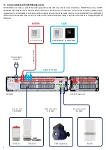
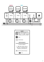
Page 9: ...Pump Boiler Boiler connection Boiler s contacts for ON OFF thermostat according to the boiler s instructions L AC230V L N N 1 8 Strefy 1 8 Strefy 1 8 Strefy KL08NSB Pump Boiler Power L N SL T30NC L N...

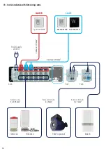
Page 10: ...THB23030 T30NC230 Power Supply 230V AC Actuators wires 2 x 0 75mm2 Pump control wires 2 x 1mm2 Boiler control wires 2 x 1mm2 KL06 PL07 PL06 PUMP optional BOILER 4 wires x 0 75 mm2 4 wires x 0 75 mm2 S...

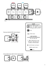
Page 11: ...L06 M Power L N L N T30NC max 6 na stref RT10 RT20 Np Np L N 1 6 Strefy PL06 L N L N T30NC max 6 na stref RT520 COM NO lub NC NO POD CZENIE KOT A L AC 230V L N N 1 6 Strefy KL06 M Power L N L N T30NC...

Page 12: ...VS35B thermostat doesn t work asaSLAVEgroupthermostat noeffectfrompotentialMASTERthermostat whichmeansthatitcanbejustasimplepump boileroractuatorcontroller PLEASE NOTE The same operating rules apply...

Page 13: ...oiler connection Boiler s contacts for ON OFF thermostat according to the boiler s instructions L AC230V L N N 1 8 Strefy 1 8 Strefy 1 8 Strefy KL08NSB Pump Boiler Power L N SL T30NC L N SL T30NC L N...

Page 14: ...ltage thermostat to a boiler or other device with an ON OFF contact VS35W VS35B BOILER CONNECTION input III B work with RM 16A relay module connection to a solid fuel boiler controller PLEASE NOTE Act...

Page 15: ...trefy KL08NSB Power L N L N SL MA 16 5 input VS35W VS35B III C work with RM 16A relay module connecting an electrical device with a higher power than the thermostat relay allows PLEASE NOTE The maximu...

Page 16: ...ture 10 Keylock 11 Settings 12 Additionaltemperaturesensor 13 Cooling 14 Heating OR 1 Increase or decrease setpoint temperature 2 Increase or decrease Day Clock Timer Party and Holiday 3 Select instal...

Page 17: ...ll display the software version 3 3 First power up sequence display will show all icons After all the main screen will be displayed To power on the thermostat you have to connect it to the 230V power...

Page 18: ...se Actingaloneworks as a manual mode Economic temperature mode pre defined setpoint temperature Usually set at night or when we are out of the house Acting alone works as a manual mode Temperature ran...

Page 19: ...intherange from 3 0 C to 3 0 C in 0 5 C steps To calibrate thermostat s temperature sensor please follow steps below 3 sec 1 2 5 4 Set temperature calibration value using and buttons To increase decre...

Page 20: ...ool mode change Use button to go to Heating Cooling choice screen 3 sec Hold button for 3 seconds to enter the menu Enter menu by button choose Heating Cooling mode using button and confirm selection...

Page 21: ...of the system It is an advanced algorithm designed to precisely maintain room temperature 1 SPAN 0 5 C 1 F 2 SPAN 1 C 1 5 F d02 Offset temperature 3 0 C to 3 0 C Offset room temperature measuring is...

Page 22: ...tain frost protection setpoint temperature specified in thermostat settings When thermostat works in Frost protection mode then you have no possibilities to change temperature setpoint 5 0 C d12 Heati...

Page 23: ...tons to choose code 47 Hold buttons for 5 seconds to enter the installer mode 7 Factory Reset To RESETVS35W VS35B thermostat to it s factory default settings please follow steps below 1 2 3 4 7 5 6 th...

Page 24: ...S2 input check the wiring If floor sensor is not connected check the D03 D04 parameters settings Err04 Floor sensor is shorted Check floor sensor wire insulation for any damages Sensor resistance for...

Page 25: ...aintenance Periodically theoutercasingcanbewipedcleanusingadrycloth pleaseDONOTuse solvents polishes detergentsorabrasivecleaners asthesecandamagethethermostat Therearenouserserviceablepartswithintheu...

Page 26: ...illbefreefromanydefectinmaterialsorworkmanship andshallperforminaccordancewithitsspecification foraperiodoffiveyearsfromthedateofinstallation SALUSControlssoleliabilityforbreachofthiswarrantywillbe at...

Page 27: ......

Page 28: ...OLS Sp z o o Sp k Rolna 4 43 262 Kobielice Poland www salus controls com SALUS Controls is a member of the Computime Group Maintaining a policy of continuous product development SALUS Controls plc res...

Reviews: