4
Plumbing
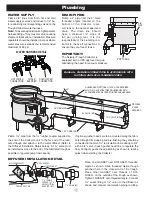
WATER
BLENDER
WATER HARNESS DETAIL
HOT WATER
CONNECTION
COLD WATER
CONNECTION
2" NPT DRAIN
AIR
GAP
WATER
BLENDER
WATER HARNESS DETAIL
HOT WATER
CONNECTION
COLD WATER
CONNECTION
2" NPT DRAIN
AIR
GAP
WATER SUPPLY
Plumb 3/4” lines from both hot and cold
water supply sources and reduce to 1/2” be-
fore attaching to corresponding valves on the
Trough Collector water harness.
Note: To assure against leaks, tighten water
harness fittings. They may come loose during
shipment, fabrication or installation. Pressure
regulators should be installed in areas where
water pressure exceeds the recommended
maximum of 80 psi.
DRAIN PIPING
Plumb a 2” pipe from the 2” male
threaded nipple located on the
bottom of the Collector reser-
voir tank to the nearest approved
drain. The drain line should
have a minimum 1/4” slope of
fall per running foot. It is the
responsibility of the plumbing con-
tractor to check all connections to
ensure they are free of leaks.
DIFFUSER INSTALLATION DETAIL
IMPORTANT!
The Salvajor Trough Collector is
equipped with a UPC approved air gap,
eliminating the need for vacuum breakers.
Plumb 1½” pipe from the 1½” rubber coupler supplied on
the end of the Collector unit to the far end of the fabri-
cated trough and attach it to the water diffuser (Refer to
the Diffuser Installation Detail below). A 1½” valve must
be installed as close to the end of the fabricated trough as
possible to regulate pump flow capacity.
If optional gusher heads are to be mounted along the fabri-
cated trough for scrapping and pre-flushing, they should be
connected to the main 1½” recirculation line reducing to 3/4”
with a 3/4” valve in each gusher head line to regulate the
flow. Configure gusher head plumbing as shown to reduce
splash when starting the Collector.
1
1
/
2
" FEMALE
THREAD to 1
1
/
2
"
SWEAT FITTING
ADAPTER (NF)
1
1
/
2
" UNION (NF)
#TVD3 GASKET
#TVD2 LOCKNUT
TROUGH SECTION
3”
MIN.
DIFFUSER #980061
Place one GASKET over DIFFUSER threaded
nipple as shown. Slide threaded nipple though
punched hole in the closed end of the trough.
Place other GASKET over threads of DIF-
FUSER, on the outside of the trough as shown.
Tighten LOCKNUT onto threaded nipple. Connect
1½” sweat fitting or 1½” union to the diffuser as
shown and connect recirculation piping to fitting.
GUSHER HEAD (OPTIONAL) 1-5/16” HOLE REQUIRED.
ALLOW 3 TO 4 FEET BETWEEN GUSHER HEADS TO
ACCOMMODATE ONE OPERATOR PER GUSHER HEAD.
DIFFUSER
2” HOLE
REQUIRED
3/4” VALVE (NF)
3/4” PIPING (NF)
1-1/2” VALVE (NF)
1-1/2” PIPING (NF)
45°
MAKE ALL PLUMBING CONNECTIONS IN ACCORDANCE WITH
NATIONAL AND LOCAL PLUMBING CODES.


