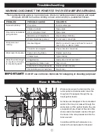
background image

Operating Instructions

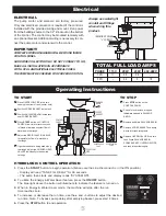
GUSHER HEAD

VALVE

RECIRCULATION

VALVE

3

B

C

SALVAGE

BASIN

CONTROL

PANEL

4 A

2
D

SCRAP

BASKET

1
E

OVERFLOW

PIPE

6

5

TO START

l

1

  Place OVERFLOW PIPE into drain


opening in bottom of tank (center hole).

l

2

  Position SCRAP BASKET inside tank.

l

3

  Position SALVAGE BASIN inside tank


over SCRAP BASKET.

l

4

 Press START button on CONTROL


PANEL. Allow time for reservoir tank


to fill and maintain a constant flow of


water down the trough.

l

5

  Adjust the RECIRCULATION VALVE


to regulate the flow of water down


the trough.

l

6

  If gusher heads are being used along


the trough, adjust the GUSHER HEAD


VALVES individually to the desired

 settings.

TO STOP

l

A

 Press STOP button on the 


CONTROL PANEL.

l

B

  Check for and remove dropped 


tableware trapped in SALVAGE  

 BASIN.

l

C

  Remove and drain SALVAGE BASIN.

l

D

  Remove SCRAP BASKET and dump


waste into trash receptacle.

l

E

  Remove OVERFLOW PIPE to drain  

 tank. 

Rinse SALVAGE BASIN,  


SCRAP BASKET, OVERFLOW PIPE,  


and tank interior thoroughly.

HYDROLOGIC CONTROL OPERATION

1.  Press the START button to begin operation. (Make sure the Line Disconnect is in the ON position)

  •  Display will read “TANK FILL DELAY” for 30 seconds.

  •  The pump then starts and display reads “SYSTEM ON”.
2.  To utilize the Energy & Water Saver feature, press the ON/OFF button.

  The blue light above the button will illuminate to indicate the feature is turned on.
3.  When in Energy & Water Saver mode, the machine will stop after the run

  time reaches zero.
4.  To increase or decrease the run time, use the + and - buttons to adjust the desired 

  run time. Note: To bypass pump delay after emptying basket, press start 2 times.
5.  Press the STOP button to end operation. 

5

Electrical

INCOMING POWER

1

/

2

" CONDUIT

PUMP

ELECTRICAL

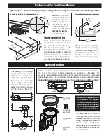
The pump motor and solenoid are factory pre-wired.

Only one electrical connection is required if the control is 

installed with the provided wiring and mount. Run power 

from the building source to the 1/2” knockout on the bottom 

of the control. The control may be mounted remotely with 

an optional bracket. Additional wiring is necessary to con-

nect the pump motor and solenoid to the control.

IMPORTANT!

COMPLETE WIRING DIAGRAMS WILL BE FOUND INSIDE 

CONTROL PANEL. 
HARD WIRE COLLECTOR ONLY. DO NOT CONNECT TO GFI.
MAKE ALL INSTALLATIONS IN ACCORDANCE

WITH LOCAL AND NATIONAL ELECTRICAL CODES.
THE PUMP MUST BE CHECKED FOR PROPER ROTATION.

Always use watertight 

conduit and fittings 

when wiring this 

product.


PHASE 115V 208V 230V 460-480V

  1 PH 

11 

5.5 

5.5 


PH – 3.2 3  1.5

TOTAL FULL LOAD AMPS
Summary of Contents for Trough Collector S419

Page 1: ...ng System 2 System Components 3 Fabricator Instructions Installation 4 Plumbing 5 Electrical Operating Instructions 6 Troubleshooting How it Works 7 Warranty 8 General Terms and Conditions of Sale FOR PRODUCT WARRANTY REGISTRATION Go to www salvajor com Click on SUPPORT at the top of homepage Click on PRODUCT REGISTRATION ALL INSTALLATIONS SHOULD BE MADE IN ACCORDANCE WITH LOCAL AND NATIONAL PLUMB...

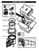
Page 2: ...ctor Hardware Diffuser Gusher Head Optional Note Drain piping recirculation piping and trough not furnished Collector Top May ship separate Collector Hardware Scrap Basket Shipped inside of Tank Salvage Basin Shipped inside of Tank Collector Tank x 12 Lockwasher x 12 Hex Nut 2 ...

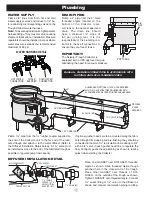
Page 3: ...ng is necessary for remote location of the control CONTROL CONTROL CONTROL CONTROL Weld the Trough Col lector top into the table using these dimensions for the table cut out Note Before welding confirm that there is a minimum of 22 above the Collector top for basket removal Upon request the Collector top may be shipped separately to a fabricator for welding to table ADJUSTABLE LEGS COLLECTOR TANK ...

Page 4: ...e Collector unit to the far end of the fabri cated trough and attach it to the water diffuser Refer to the Diffuser Installation Detail below A 1 valve must be installed as close to the end of the fabricated trough as possible to regulate pump flow capacity If optional gusher heads are to be mounted along the fabri cated trough for scrapping and pre flushing they should be connected to the main 1 ...

Page 5: ... for 30 seconds The pump then starts and display reads SYSTEM ON 2 To utilize the Energy Water Saver feature press the ON OFF button The blue light above the button will illuminate to indicate the feature is turned on 3 When in Energy Water Saver mode the machine will stop after the run time reaches zero 4 To increase or decrease the run time use the and buttons to adjust the desired run time Note...

Page 6: ... is going into tank Pump motor not running Water leaks from pump Water flow down trough is very slow or Collector is not pumping water Drain open Valves are closed Hot or cold valve closed Blender is out of adjustment Water connections reversed Overload tripped Contactor not energized Pump seal o ring broken Clamps loose Clogged pump Clogged pump intake screen Pump motor running backwards Recircul...

Page 7: ...s unaltered has been properly installed maintained and operated Salvajor will repair or replace at no cost defective parts due to material or workmanship if such service is performed by a Salvajor Authorized Service Center Parts wear is not considered a defect Conditions not covered by this warranty Faulty or improper electrical installations faulty or improper plumbing installations disposer jamm...

Page 8: ...ability to Buyer and or its customers exceed the price paid by Buyer for the specific goods provided by Seller giving rise to the claim or cause of action Buyer agrees that in no event shall seller s liability to buyer and or its customers ex tend to include incidental consequential or punitive damages The term consequential damages shall include without limitation loss of anticipated profits busi...

Reviews: