background image


REVISED 5/19/2017   


          © SAM CARBIS SOLUTIONS GROUP, LLC, 2017, WITH ALL RIGHTS RESERVED 


    PAGE 20 


6)


OPERATION 


a)


GENERAL


i)


For systems that include loading arms, see separate instruction manual for operation of the loading arms. 


ii)


The gangway design load limit is 500 lbs., single person occupancy. 


iii)


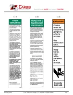
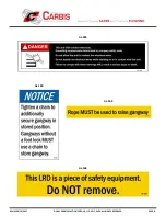
Verify that all safety placards, signs, and decals are clearly visible, legible, and in good repair. Operating 

personnel must be familiar with the contents of such placards, signs, and decals.  See section 

3) 

IMPORTANT SAFETY INFORMATION

 v)


SAFETY SIGN DESCRIPTIONS for the description of all safety signs 

that appear on the equipment described in this manual. 


b)


PRE-OPERATIONAL SAFETY INFORMATION 


Following are the pre-operational safety messages grouped by hazard: 


i)


(1)


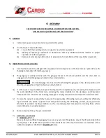
This equipment CAN conduct electricity. 

(a)


Any grounding that may be required is to be performed per the owner’s safety code. 

(b)


Do NOT allow this unit to come in contact with live electrical wires. 

(c)


Do NOT handle live electrical wires while standing on or in contact with this unit. 


Failure to comply with these warnings WILL result in serious injury or death.


ii)


(1)


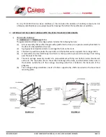
Correct vehicle positioning and proper deployment of Carbis equipment are imperative to its 

function. Incorrectly positioned vehicles, or improper use of this equipment, increase the risk of 

serious injury or death.  Carbis equipment is designed to function only as described in the manual 

and depicted on the drawings.  

IT IS THE SOLE RESPONSIBILITY OF THE OWNER TO ENSURE PROPER 

USE OF CARBIS EQUIPMENT.


(2)


Before accessing Carbis equipment, a vehicle must be in the correctly spotted position and the 

Carbis equipment properly deployed, supported, and secured. 

(3)


Personnel must not access Carbis equipment during any controlled operation. 

(4)


Nonessential


personnel must stay clear of Carbis equipment during any controlled operation. 

(5)


Operator must be certain that nonessential personnel are clear of Carbis equipment during any 

controlled operation. 

(6)


Operator must not place Carbis equipment in motion while occupying the same equipment. 


     DANGER 


WARNING 

Summary of Contents for TCG-1000

Page 1: ...REVISED 5 19 2017 SAM CARBIS SOLUTIONS GROUP LLC 2017 WITH ALL RIGHTS RESERVED PAGE 1 INSTRUCTION MANUAL FOR MANUALLY OPERATED TCG 1000 GANGWAY ...

Page 2: ...S FIRST Section 2 INTRODUCTION Section 3 IMPORTANT SAFETY INFORMATION Section 4 PRODUCT DESCRIPTION Section 5 ASSEMBLY Section 6 OPERATION Section 7 MAINTENANCE Section 8 EXTENDED INSPECTION ADDENDUM Section 9 MANUAL BRAKE ADJUSTMENT ADDENDUM Section 10 LIFT RESISTING DEVICE ADDENDUM Section 11 DRAWINGS AND SPECIFICATIONS ...

Page 3: ...ual is disregarded whether inadvertently or willfully b VEHICLE POSITIONING i Carbis gangways are designed in a variety of standard styles sizes and materials to accommodate customer specific requirements in applications that include varying heights and types of vehicles Subsequently with each gangway Carbis provides customer approved Engineering Drawings and or scope data that document key dimens...

Page 4: ...oo far from the TCG 1000 This blocks access to the hatch and also creates a fall hazard SAF T Cage is installed to achieve as close to 42 as possible based upon the site specific vehicle types Cage shown in LOW position Vehicle is correctly positioned to the TCG 1000 This allows access to the hatch and also prevents a fall Cage shown in HIGH position Cage height position can be either the HIGH pos...

Page 5: ...perative that operating and maintenance personnel become familiar with the safety information contained in section 3 IMPORTANT SAFETY INFORMATION c Check that all safety placards signs and decals are clearly visible legible and in good repair Operating personnel must be familiar with the contents of such placards signs and decals See section 3 v for SAFETY SIGN DESCRIPTIONS for the description of ...

Page 6: ...HAZARDS Following are the safety messages grouped by hazard as used throughout this manual i 1 This equipment CAN conduct electricity a Any grounding that may be required is to be performed per the owner s safety code b Do NOT allow this unit to come in contact with live electrical wires c Do NOT handle live electrical wires while standing on or in contact with this unit Failure to comply with the...

Page 7: ...efully before unpacking or installing Carbis equipment 2 Only qualified personnel in good physical condition trained in the proper operation of this equipment should be permitted to operate it 3 Appropriate Personnel Protective Equipment PPE such as gloves safety glasses safety shoes etc should be worn at all times during operation of this equipment 4 For chain supported Carbis gangways both chain...

Page 8: ...REVISED 5 19 2017 SAM CARBIS SOLUTIONS GROUP LLC 2017 WITH ALL RIGHTS RESERVED PAGE 8 AL 156 AL 159 AL 157 ...

Page 9: ...REVISED 5 19 2017 SAM CARBIS SOLUTIONS GROUP LLC 2017 WITH ALL RIGHTS RESERVED PAGE 9 AL 305 AL 163 AL 162 AL 160 ...

Page 10: ...llowing features 1 A galvanized steel base tread that is either fixed mounted directly to a platform horizontally pivot mounted or track mounted 2 The gangway consists of stringers that articulate about the base tread and top handrails and midrails that pivot about the base tread uprights The outboard uprights support the outer end of the top handrails and midrails and serve as a support for safet...

Page 11: ...quipment while allowing a variety of vehicles to be accessed The chains should be used for overnight or long term storage of the gangway 7 Covered springs mounted between the uprights and the stringers provide tension adjustment to minimize the push pull force required to articulate the gangway 8 A pull up rope aids in returning the gangway to the upright stored position 9 For any gangway used in ...

Page 12: ...hat bolts to the face of a fixed platform structure 2 A gangway base tread mounted on a carriage that rolls on the track 3 The track top section captures the top rollers and the bottom section supports the carriage rollers 4 A removable stop inserted through end holes in the top surface prevents the carriage from rolling past the ends of the track 5 The main carriage assembly consists of a plate w...

Page 13: ...he gangway base tread The top of the curved release lever arm includes a bent leg that engages with the top edge of the gangway stringer as the gangway is raised to the stored position The brake pad on the brake pad pivot arm engages with the outer surface of the track on which the gangway rolls c As the gangway body is raised to the stored position the stringer engages the bent leg of the release...

Page 14: ...on mounted on the platform side of the tread and includes the following features 1 The male pivot post engages with a female pivot mounting sleeve and rests on a wear pad 2 The range of pivot rotation is 10 degrees each side of center 3 Brackets that are bolted or welded to a platform either surface mounted or underslung below the platform structure support the female pivot mounting sleeve 4 The p...

Page 15: ...REVISED 5 19 2017 SAM CARBIS SOLUTIONS GROUP LLC 2017 WITH ALL RIGHTS RESERVED PAGE 15 FIGURE 4 5 FIGURE 4 6 ...

Page 16: ... disengage the chain links from holding the gangway in the stored position until after the gangway base tread has been securely installed iii It is the owner s responsibility to inspect the shipment for completeness by comparing the shipment with the parts identified in the Parts Lists including the items identified in the Hardware and Pneumatic Component Lists Check for any shipping damages or mi...

Page 17: ...ements will be specifically detailed on the drawings b Any bolts less than 1 2 diameter torque to 60 in lbs 2 Stainless Hardware Snug Tight Condition a The snug tight condition is defined as the tightness that exists when all plies in a joint are in firm contact This may be attained by the full effort of a man using an ordinary spud wrench Carbis standard bolt installation is snug tight in a beari...

Page 18: ... engage the brake to prevent the gangway from free rolling along the track 7 Disengage the chains from holding the gangway in the stored position and reposition the chains with the next to the last link engaged in the slot of the chain lock to begin operation 8 For retrofit of the TCG S910 1 Track Lock Mechanism on an existing gangway see section 7 MAINTENANCE for the installation procedure iv PIV...

Page 19: ...gway in the stored position and reposition the chains with the next to the last link engaged in the slot of the chain lock to begin operation NOTE If cage option is included do not try to lower gangway until cage is installed vi CAGE ASSEMBLY OPTION For gangways that include safety cage options use Carbis supplied hardware to install the cage per FIGURE 5 2 below Gangway and cage type may vary fro...

Page 20: ...electrical wires c Do NOT handle live electrical wires while standing on or in contact with this unit Failure to comply with these warnings WILL result in serious injury or death ii 1 Correct vehicle positioning and proper deployment of Carbis equipment are imperative to its function Incorrectly positioned vehicles or improper use of this equipment increase the risk of serious injury or death Carb...

Page 21: ...associated with the material and to implement the appropriate safety measures to protect personnel against such hazards Failure to comply with these warnings COULD result in serious injury or death iii 1 Only qualified personnel in good physical condition trained in the proper operation of this equipment should be permitted to operate it 2 Appropriate Personnel Protective Equipment PPE such as glo...

Page 22: ...ck to release the gangway from the stored position 5 Place both hands on the top handrail and push outward while the foot lock is depressed 6 After the gangway is in the working position adjust the chains so that both chains equally support the gangway with the chain links engaged in the slots of the chain locks 7 After performing the required work and before leaving the vehicle make sure the area...

Page 23: ...ght If any fastening hardware whether factory or field installed has been loosened it is imperative that it be tightened before using the equipment 6 Check that all moving parts are properly functioning 7 Lubricate the pivot points on the handrails and main body with lightweight aerosol oil 8 These units have flanged bearings with a grease fitting the bearings should be lubricated with lithium bas...

Page 24: ...VISED 5 19 2017 SAM CARBIS SOLUTIONS GROUP LLC 2017 WITH ALL RIGHTS RESERVED PAGE 24 ii SPRING ADJUSTMENT AND REPLACEMENT 1 To adjust spring tension or replace a spring follow the instructions noted below ...

Page 25: ...ith the foot lock mechanism the procedure noted below can be used to realign the locking pin with the foot lock mechanism ii The following procedure applies to all Carbis pneumatically operated and manually operated TCG 1000 TCG 2000 and TCG 2500 Series gangways with single or double foot locks 1 For safety reasons make sure the system is properly locked and tagged to prevent inadvertent gangway o...

Page 26: ... arm engages the top edge of the stringer 6 With the gangway body in the raised stored position check that the brake pad is free of the roller track and that the gangway will freely roll when manually pushed in either direction 7 Check the brake pad function by lowering the gangway body from the stored position sufficient to completely disengage the release lever arm from the gangway stringer At t...

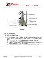
Page 27: ...is label to the upper portion of the left hand upright of the gangway base tread near the manual track lock lever FIGURE 7 1 NOTICE RELEASE LEVER ARM BENT LEG CARBIS SUPPLIED WARNING LABEL CARBIS SUPPLIED MOUNTING HARDWARE BRAKE PADS HOUSING BASE TREAD SIDE PLATE BOLT HOLES GANGWAY STRINGER TOP EDGE CARBIS SUPPLIED MOUNTING HARDWARE CARBIS SUPPLIED MOUNTING HARDWARE FOR MANUAL TRACK LOCK MANUAL TR...

Page 28: ... dry condition 5 Check all bolted connections First make certain that none can be hand loosened then check the connections again using a wrench to make certain they are securely snug 6 Check all rotating pivoting connections for fit corrosion excessive wear and for lubrication where required Replace any fitting whose condition so warrants and lubricate components as needed 7 Where rolling componen...

Page 29: ...cient to prevent the gangway from tracking while the gangway is in the upright stored position or if the brake lever becomes too tight to engage the brake pad the manual brake can be adjusted per the procedure below to lock the gangway in place with the appropriate brake engagement while the gangway is in the upright stored position For the purpose of describing the adjustment procedure the follow...

Page 30: ... a push pull test tool is available a properly adjusted manual lock braking mechanism was shop tested to resist 300 lbs of push pull force 5 If the brake engagement is insufficient or if the lever is still too tight repeat steps 1 thru 4 to achieve the desired results FIGURE 9 1 MANUAL BRAKE SUB ASSEMBLY OF THE TCG S910 1 TRACK LOCK MECHANISM ii For any assistance replacement parts comments or que...

Page 31: ...The Lift Resisting Device consists of the following features 1 A linear rail with ratcheting angled teeth mounted on the underside the rail is pinned on one end to a lug that is supported on the top rail of the gangway by double U bolts The opposite end of the rail slides into an extension tube that is pinned to a support bolted to the outboard handrail of the gangway 2 Pinned to a lug mounted on ...

Page 32: ... platform side of the handrail pivot bracket as shown in FIGURE 10 1 With the LRD totally assembled center the linear rail mounting bracket at the location marked Install the two U bolts spacers and washers as supplied and tighten e Test the operation of the Lever Arm Release Handle by raising and lowering the gangway Pull the LRD rope to disengage the locking mechanism in order to raise the gangw...

Page 33: ...REVISED 5 19 2017 SAM CARBIS SOLUTIONS GROUP LLC 2017 WITH ALL RIGHTS RESERVED PAGE 33 FIGURE 10 1 ...

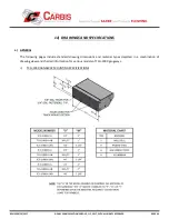
Page 34: ...VED PAGE 34 11 DRAWINGS AND SPECIFICATIONS a GENERAL The following pages include standard drawing dimensions and material types depicted in a combination of drawing views and charted information for various models of TCG 1000 gangways i TCG 1000 GANGWAY MOUNTING SPECIFICATIONS ...

Page 35: ...REVISED 5 19 2017 SAM CARBIS SOLUTIONS GROUP LLC 2017 WITH ALL RIGHTS RESERVED PAGE 35 ii TCG 1000 GANGWAY GENERAL ARRANGEMENT ...

Page 36: ...REVISED 5 19 2017 SAM CARBIS SOLUTIONS GROUP LLC 2017 WITH ALL RIGHTS RESERVED PAGE 36 iii TCG 1000 GANGWAY MODEL SPECIFICATIONS ...

Reviews: