REVISED 5/19/2017
© SAM CARBIS SOLUTIONS GROUP, LLC, 2017, WITH ALL RIGHTS RESERVED
PAGE 26
d)
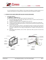
TCG-S910.1 TRACK LOCK MECHANISM
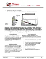
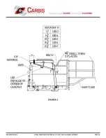
See
FIGURE 7-1
below.
i)
The following maintenance procedure applies to both the replacement of an existing TCG-S910.1 Track
Lock Mechanism or the new installation of the TCG-S910.1 Track Lock Mechanism as a retrofit on an
existing tracking gangway system.
ii)
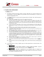
Using
FIGURE 7-1
below as a guide, install the replacement/new TCG-S910.1 Track Lock Mechanism per
the following steps:
(1)
Make certain the gangway body is locked in the upright stored position.
(2)
Manually pivot the curved release lever arm sufficient so that it will engage the top edge of the
stringer on the stored gangway. If the lever arm is too tight to manually hold, temporarily tie the
top bend of the arm to the pivot bolt of the brake pad using string or tape that is sufficiently strong
to hold the arm in place.
(3)
Position the Track Lock Assembly so that the lever arm bent leg passes over the top edge of the
stored gangway stringer as the bolt sleeves are aligned with the bolt holes on the base tread side
plate.
(4)
Using the Carbis-supplied hardware, bolt the assembly to the base tread side plate.
(5)
If the release lever arm was tied back, release the tie so that the bent leg of the release lever arm
engages the top edge of the stringer.
(6)
With the gangway body in the raised stored position, check that the brake pad is free of the roller
track and that the gangway will freely roll when manually pushed in either direction.
(7)
Check the brake pad function by lowering the gangway body from the stored position sufficient to
completely disengage the release lever arm from the gangway stringer. At that point, the brake pad
should be maximally engaged with the roller track to prevent the gangway from tracking. Apply
sufficient push/pull pressure on the gangway to verify that the gangway remains in position without
rolling in either direction.
(8)
Raise and lower the gangway to and from the stored position several times to confirm the
consistency of the TCG-S910.1 Track Lock Mechanism function.
(9)
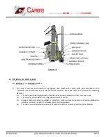
Install the manual track lock lever and Carbis-supplied mounting hardware as shown in
FIGURE 7-1
below.
(10)
Verify that the manual track lock brake engages with the track sufficient to firmly hold the gangway
in place.
iii)
If the safety labels are missing or illegible, apply the Carbis-supplied labels as described below in the
positions noted:
(1)
DO NOT OPERATE GANGWAY IF SPRING IS BROKEN OR MISSING. Apply this
label (with the black arrow) on the mechanism as shown in
FIGURE 7-1
below.
(2)
THIS UNIT IS EQUIPPED WITH AN AUTOMATIC BRAKE TO PREVENT THE
GANGWAY FROM TRACKING WHILE DEPLOYED. Apply this label to the lower portion of the left-
hand upright of the gangway base tread.
WARNING
!
WARNING
!

