REVISED 5/19/2017
© SAM CARBIS SOLUTIONS GROUP, LLC, 2017, WITH ALL RIGHTS RESERVED
PAGE 30
(3)
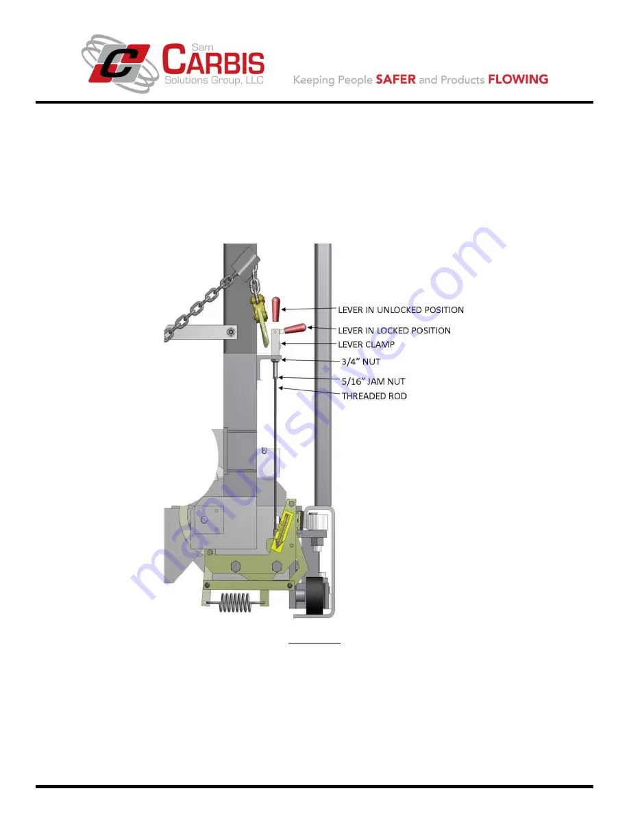
With the lever in the upright unlocked position, secure the lever clamp in place and tighten the 3/4”
nut on the lever clamp first, and then tighten the 5/16” jam nut on the threaded rod.
(4)
Push the lever down to the horizontal locked position and test the brake engagement. If a push-pull
test tool is available, a properly adjusted manual lock braking mechanism was shop tested to resist
300 lbs. of push-pull force.
(5)
If the brake engagement is insufficient, or if the lever is still too tight, repeat steps (1) thru (4) to
achieve the desired results.
FIGURE 9-1
MANUAL BRAKE SUB-ASSEMBLY
OF THE TCG-S910.1 TRACK LOCK MECHANISM
ii)
For any assistance, replacement parts, comments, or questions, call Carbis’ Customer Service Department
at 1-800-845-2387. Please have your model number, serial number, or drawing number available to
expedite your request.

