17
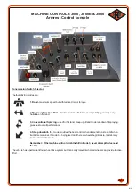
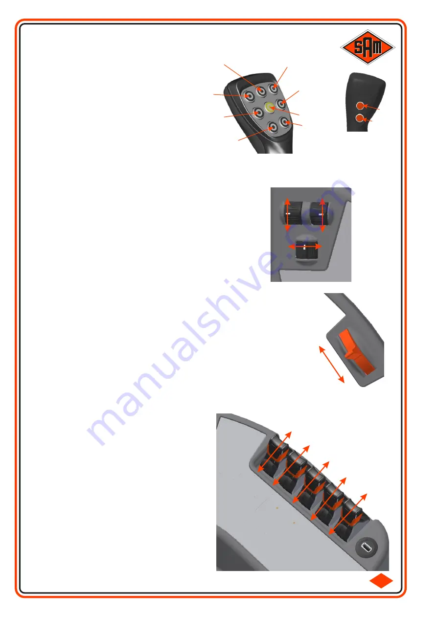
Section 5
(Section 4 if
only 5 sections)
Section 4
(Section 3
if only 5
sections)
Section 6
(Section 5 if
only 5 Sections)
Section 3
(Section 2 if
only 5 sections)
Main ON/OFF
Section 2
(Section 1 if
only 5 sections)
Section 7
(RH Incline if
only 5 sections)
(RH Indicator in
Road Mode)
Section 1
(LH Incline if
only 5 sections)
(LH Indicator in
Road Mode)
RPM +
RPM -
The Engine Throttle control is a rotary wheel, which when moved in the forward
direction, the Engine RPM is increased. When moved in the rearward direction
the Engine RPM is decreased. The rotary wheel will remain in the position it was
left in, except in the case of the Horizon 5500. In this case the rotary wheel will
return to the central position because it operates in a momentary fashion. When
moved in the forward / rearward direction momentarily, the rpm will increase /
decrease in according steps, if held in position the RPM will change more rapidly.
The Engine Throttle will only operate while in Field Mode, as when in Road Mode
the RPM is controlled via the Joystick / Travel Pedal.
If the Engine Throttle was not at idle before switching to Road Mode, when
switching back to Field Mode the Engine Speed will return to the original RPM.
ARMREST CONTROL CONSOLE Cont..........
The Boom Fold Switches are a lever type switch.
When they are moved to the left (towards the
operator) the Boom section will fold IN. When moved
to the right (away from the operator) the Boom section
will fold OUT.
1st fold
= Main Section (12m)
2nd fold
= Mid Section (24m)
3rd fold
= End Section (30/32/36m)
4th fold
= Hydraulic Flip (24-28m, 30-32m, 36-40m)
3rd fold
when a 24m Independent Fold Boom is fitted
= Left Hand Independent.
4th fold
when a 24m Independent Fold Boom is fitted
= Right Hand Independent.
4th fold
when a 30-36m Independent Fold Boom is
fitted = Left Hand Independent.
5th fold
when a 30-36m Independent Fold Boom is
fitted = Right Hand Independent.
1st
Fold
Out
2nd
Fold
Out
3rd
Fold
Out
4th
Fold
Out
5th
Fold
Out
1st Fold In
2nd Fold In
3rd Fold In
4th Fold In
5th Fold In
2.1-3
LEFT
INCLINE
UP
RIGHT
INCLINE
UP
LEFT
INCLINE
DOWN
CONTOUR
LEFT
CONTOUR
RIGHT
RIGHT
INCLINE
DOWN
The Boom Incline switches (where fitted) are a roller type
switch. Moving the switches forwards, inclines the boom UP.
Moving the switches rearwards, inclines the boom DOWN.
The Contour Switch (where fitted) is a roller type switch.
Moving the switch to the left, contours the boom to the LEFT.
Moving the switch to the right, contours the boom to the
RIGHT. If no switch is fitted and while Field Mode is selected,
Section 1 becomes Left Contour and Section 7 becomes
Right Contour.
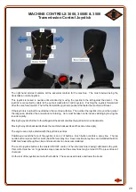
The 8 buttons on the front face of the Joystick
are Spray Boom Nozzle Sections. Buttons are
active when they are illuminated Green / Blue.
On the rear face are 2 more Buttons, which
control the Height of the Boom Assembly.
The centre Joystick button is the Main Spray
(master) On/Off control.
When in Road Mode Section 1 becomes the
Left Hand Indicator and Section 7 becomes the
Right Hand Indicator. They are not self
cancelling.
Boom UP
Boom Down
Summary of Contents for Horizon
Page 5: ...4 SECTION 1 SAFETY ...
Page 14: ...13 ...
Page 15: ...14 SECTION 2 MACHINE CONTROLS 2 1 4000 4000E 5500 6000 MACHINES 2 2 3000 3000E 3500 MACHINE ...
Page 32: ...31 SECTION 3 MECHANICAL COMPONENTS ...
Page 40: ...39 3 8 TYRES LOAD INDEX TABLE ...
Page 45: ...44 ...
Page 46: ...45 SECTION 4 SPRAYING COMPONENTS ...
Page 53: ...52 SECTION 5 SPRAYING ...
Page 58: ...57 ...
Page 59: ...58 SECTION 6 6 1 MAINTENANCE 6 2 Fuses for 3000 3000E 3500 Machine ...


