


40
Dual wheels are a poor alternative to flotation wheels. They are less flexible than the single wheel option and
transmit very high shock loads into associated components. SAM would suggest a 30% reduction in speed
be implemented.
DUAL WHEELS
All standard sprayers have the same track capability via adjustable axles 1830mm (72”) – 2135mm (84”) in
102mm (4”) increments, i.e. 51mm (2”) per wheel.
Non standard sprayers may have 1730mm (68") – 2030mm (80") adjustable axles.
Note - Track Widths may differ if different wheel rim offsets have been specified, e.g a 68" - 80" axle may
achieve 70" - 82" instead.
TRACK ADJUSTMENT
The engine must be stopped, the
parking brake applied
and the front wheels chocked.
Lift one end of the machine until the tyres are clear of the ground. Loosen the two clamps at either end of the
axle beam.
Caution: Ensure the machine is well supported. A single jack under the centre of the axle is not
acceptable.
Remove the four bolts in the bottom of the axle beam.
Remove the two track rod adjusting bolts.
In the bottom face of the axle beam are two slots and in each slot is a screwed stop (screwed into the sliding
leg). If the stop is allowed to slide from one side of the slot to the other then the movement will be 6” (152mm).
This equates to 12” (305mm) over the complete axle. However, if the stop is moved to either of the two other
positions within the slot then the movement is reduced to 4” (102mm) or 2” (51mm).
Pull the sliding legs to the required position.
Pull the track rods to the correct position and refit the securing bolts.
Refit and lightly tighten the four screws in the bottom of the axle beam. Lightly re-tighten the clamps at the end
of the axle beam. Lower the machine to the ground and fully tighten clamps and fixing screws.
Repeat this exercise on the second axle.
RE-CHECK THE BOLT TENSION AFTER THE FIRST HOUR'S WORK.
MANUAL SLIDING AXLES
3-9
Summary of Contents for Horizon
Page 5: ...4 SECTION 1 SAFETY ...
Page 14: ...13 ...
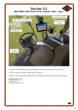
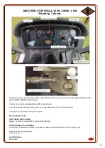
Page 15: ...14 SECTION 2 MACHINE CONTROLS 2 1 4000 4000E 5500 6000 MACHINES 2 2 3000 3000E 3500 MACHINE ...
Page 32: ...31 SECTION 3 MECHANICAL COMPONENTS ...
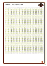
Page 40: ...39 3 8 TYRES LOAD INDEX TABLE ...
Page 45: ...44 ...
Page 46: ...45 SECTION 4 SPRAYING COMPONENTS ...
Page 53: ...52 SECTION 5 SPRAYING ...
Page 58: ...57 ...
Page 59: ...58 SECTION 6 6 1 MAINTENANCE 6 2 Fuses for 3000 3000E 3500 Machine ...


