background image

SAM4S ER-150 


9-1


9 Schematic Diagrams 

4

Da

te

of

4

3

2

1

AB

Si

ze

3

2

1

B

Dr

aw

by

S

heet

C

TI

TL

E

 :


D

C

D

Fi

le 

Na

m

e

A3

Re

v

Sh

in 

H

eung 

Pr

ec

isi

on 

Co

.,

 Lt

d.

2

1

FI

LM

G7

G4

G1

Pg

Pd

Pa

G7

G4

G1

Pg

Pd

Pa

3

2

1

6

5

4

9

8

7

0

C

1

3

4

56

7

8

9

VL

G

G8

G5

G2

G6

G9

G3

Ph

Pe

Pb

Pc

Pf

VF

1

G2

G3

G5

G6

G8

G9

Pb

Pc

Pe

Pf

PR

I N

TE

M-

42V

SP

OO

L

VL

G

VF

2

FG

97D6 

( R

ear  9 

Di

gi t )

VL

G

BAC

KU

P

2

CN3

:B

SO

L

E

MO

T

O

R

FB

3

FI

LM

FB

2

B

U

ZZE

R

1

CN1

:A

CO

N-

BO

X;

2P

,2.

5

MM,

ST

DRA

W

E

R

1N

4148

D1

9

1N

4148

D1

8

1N

4148

D1

4

[X]

[Z]

[O

FF]

00

DP

T

1

TO

TA

L

TE

N

D

VD

%

F

EED

E

R

150 

MA

IN.

SC

H

ER

-150 

MA

IN

1

B

U

ZZE

R

B

A

TTE

R

Y

1

CN3

:A

CO

N-

BO

X;

2P

,2.

5

MM,

ST

AA

SEN

#

1

SEN

#

2

SEN

#

3

MO

T

O

R

2

CN2

:B

100nF

C2

0

C7

470uF

16V

100nF

C2

6

VM

T

F

U

SE1

250V

,2A

C5

1000uF

16V

R1

3

1.

8K

R1

4

1.

8K

UZ

4.7B

D9

270

R2

C6

47uF

50V

C1

3

10nF

C1

4

10nF

C1

5

10nF

VM

T

VL

G

VL

G

10pF

C1

8

VL

G

R3

0

10K

VL

G

VL

G

1

3

2

K

S

C

945-

G

Q4

62K

R1

8

1

3

2

K

S

C

945-

G

Q1

0

VL

G

VF

2

C2

2

100nF

VL

G

2

CN1

:B

62K

R5

VL

G

R-

AR

R

AY 

150K

1N

4148

D2

0

VL

G

1N

4148

D1

6

1N

4148

D1

5

1N

4148

D1

3

VL

G

10K

R2

3

10K

R9

4.

7uF

50V

C4

[P]

VL

G

X/

RF

TA

X

CH

P

O

RA

SU

B

C

ASH

#/

NS

2004.

02.

09

10nF

C1

9

200K

R2

1

C2

5

10nF

C-

AR

R

AY 

100pF

V4

.0

680

R2

2

270

R3

5

VR

AW

1N

4003

D3

4700uF

35V

C1

1N

4003

D1

0

VM

T

4700uF

35V

C2

100nF

C1

0

VBK

1

3

2

KS

C945-

G

Q2

1N

4003

D7

ZD

12BM

D5

VF

1

VL

G

C1

1

100nF

VL

G

VD

SP

R1

0

4.

7K

1/

2W

13

12

74LS14

U2

: F

7.

5K

R1

7

FG

97D6 

( Fr

ont  9 

Di

gi t )

5.

6K

R2

0

10K

R8

1N

4148

D1

7

51K

R7

47K

R2

5

R2

4

10K

KEY 

B'

D

R2

6

2K

VL

G

MO

D

E

PO

W

E

R

 T

R

AN

SF

O

R

M

E

R

FB

1

FB

5

7

FB

4

4

[CO

M

]

DP

T

2

1

CO

N-

BO

X;

2P

,2.

5

MM,

ST

CN2

:A

PO

W

E

R

 PC

B

R4

330

1

3

2

TI P

31C 
Q1

1

1N

4751A

D6

S

epar

at

GN

D

1N

4148

D1

2

D1

1

1N

4148

5

6

8

1K

R1

2

1K

R1

1

1K

R1

5

R1

6

1.

8K

2

3

1

CO

N-

BO

X;

8P

,2.

5

MM,

ST

CN5

:A

2

1

CN4

:A

CO

N-

BO

X;

2P

,2.

5

MM,

ST

X1

4M

H

Z

R6

1M

10pF

C1

7

4.

7K

R2

7

R2

9

2.

2K

1uF

50V

C8

100nF

C1

6

R1

1K

100nF

C3

11

10

74LS

14

U2

:E

9

8

74LS

14

U2

:D

5

6

U2

:C

74LS

14

3

4

U2

:B

74LS

14

C

104

100nF

VD

SP

MA

IN 

S

CHE

M

A

T

IC

VR

AW

B

U

ZZE

R

62K

R1

9

1

3

2

K

S

C

945-

G

Q1

[RE

G

]

270

R3

1

C2

4

10nF

C2

3

10nF

H

y

un-

Oh

,Yu

n

PKM

2

4

S

P

1N

4003

D4

R3

1K

C1

2

100nF

100nF

C9

1

4

2

3

D1

2K

B

P

02M

7

OU

T

2

6

OU

T

3

3

IN3

2

IN2

5

VC

C

8

OU

T

1

1

IN1

4

GN

D

U3

LB

1268

R4

0

15

100K

R2

8

100nF

C2

7

1

3

2

Q3

KS

C945-

G

SE

M100(

61408)

D8

1N

4003

1

2

7

14

74LS

14

U2

:A

OP

T

ION

1

3

2

K

S

C

945-

G

Q7

1

3

2

K

S

C

945-

G

Q8

VL

G

13

RA

1

44

TE

ST

26

VC

C

18

R5

0

17

nI

NT

1

14

R3

0

15

R3

1

23

R6

1

43

R

ESET

22

R6

0

29

R4

2

28

R4

1

42

R9

3

39

R9

0

40

R9

1

32

R7

1

31

R7

0

35

R8

0

34

R7

3

38

R8

3

37

R8

2

57

D9

56

D8

60

D1

2

59

D1

1

63

D1

5

62

D1

4

4

R1

0

8

R2

0

7

R1

3

6

R1

2

11

R2

3

10

R2

2

47

GN

D

16

nI

NT

0

50

D2

51

D3

27

R4

0

30

R4

3

41

R9

2

33

R7

2

36

R8

1

55

D7

58

D1

0

61

D1

3

5

R1

1

9

R2

1

45

OS

C1

46

OS

C2

U1

1

3

2

K

S

C

945-

G

Q5

1

3

2

K

S

C

945-

G

Q9

CO

NV

E

R

T

E

R(

6.

6V

/5V

/30V

)

3

2

1

Q6

K

S

D

288-

Y


Summary of Contents for ER-150

Page 1: ...TRONIC CASH REGISTER Manual 1 Precaution Statements 2 Product Specifications 3 Installation and Operation 4 Assembly and Disassembly 5 Exploded View and Part List 6 PCB Layout and Part List 7 Block di...

Page 2: ......

Page 3: ...this manual is subject to change without prior notice Therefore you must check the correspondence of your manual with your machine No part of this manual may be copied or reproduced in any form or by...

Page 4: ...ctronic Cash Register Notes Notes may appear anywhere in the manual They describe additional information about the item Precaution symbols Indicates a Safety Precaution that applies to this part compo...

Page 5: ...nual may not in whole or in part be copied photocopied reproduced translated or converted to any electronic or machine readable from without prior written permission of Shin Heung Precision SAM4S ER 1...

Page 6: ...and especially the AC and high voltage supplies Always inspect for pinched out of place or frayed wiring Do not change the spacing between comp onents and the printed circuit board Check the AC power...

Page 7: ...rument s ground lead to the instrument chassis ground before connecting the positive lead always remove the instrument s ground lead last 1 3 Precautions for Electrostatic Sensitive Devices ESDs 1 Som...

Page 8: ...AC230V 50Hz USA Europe Rating 8W USA and Europe Printer M 42V Refer to Printer Specification on next page Battery AA Size 2 Processor SEM100 64pin Masked Processor Memory 61408 Display Front 9 digits...

Page 9: ...t Ordinary type 57 5 0 5 mm 80mm or below 0 06 0 85mm 47 64 g 40 55 kg 1000 sheets 1091 x 788mm Paper Feeding Quick feed Approx 8 Line sec Paper release mechanism attached Ink Roll Color Life Standard...

Page 10: ...2 Product Specifications SAM4S ER 150 2 3 2 2 Appearance 2 2 A Appearance Dimensions mm 2 2 B ECR Features Cover Printer Key Board Drawer Window display Case Upper Power Cord...

Page 11: ...2 Product Specifications 2 4 SAM4S ER 150 Memo...

Page 12: ...ector is plugged off the System Reset must be performed before operation Plug in while pressing the c and 00 keys in 3 seconds at P mode Then ER 150 system will be reset and all data will be cleared 3...

Page 13: ...shows the various mofes that are available Mode Function OFF Operation stop R Sales Operation X X level report generation Z Z level report generation P Program mode Table 3 1 ECR Modes Figure 3 1 Mode...

Page 14: ...pter 5 1 Total Disassembly 1 Lift off Cover printer A Page 5 1 2 Remove two screws C 8 on Case upper C 9 and pull it front and up then the Case upper C 9 will be open Page 5 5 3 Remove the Power conne...

Page 15: ...4 Assembly and Disassembly 4 2 SAM4S ER 150 Memo...

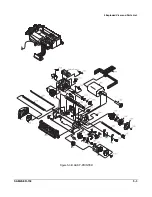
Page 16: ...SAM4S ER 150 5 1 5 Exploded View and Parts List Figure5 1 Total Disassembly...

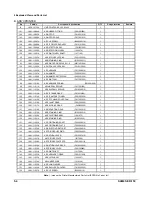
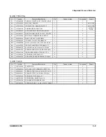
Page 17: ...COVER PRINTER A ASS Y COVER PRINTER No Parts No Description Specification Q ty Design Location Serviceable Remark JK97 00924A MEA COVER PRINT ER 150 BASIC WORLD 1 Y JK70 10320A IPR CUTTER PAPER ER 150...

Page 18: ...5 Exploded View and Parts List SAM4S ER 150 5 3 Figure5 3 B ASS Y PRINTER...

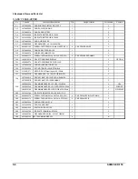
Page 19: ...09010 1 122 JK81 11013A AS P F TRANS GEAR F815212010 1 123 JK81 11014A AS P F RATCHET WHEEL F801202030 1 124 JK81 11015A AS PRT CHANGE OVER CAM F817203020 1 125 JK81 11016A AS PLANET GEAR F801206020 1...

Page 20: ...5 Exploded View and Parts List SAM4S ER 150 5 5 Figure5 4 C ASS Y CASE UPPER...

Page 21: ...150R 1 Y C 14 JK72 40932A PMO HOLDER MOTOR ER 150 1 Y C 15 JK73 30200A RCT MOTOR ER 150 URETAN BLK 1 Y C 16 3101 001071 MOTOR DC 3270rpm 16g cm 9V 130mA 1 Y C 17 JK39 40303B CBF HARNESS UL 1061 30 100...

Page 22: ...1 SCREW TAPTITE PWH S M4 L8 ZPC YEL 1 DRAWER POWER TRANS Y JK26 30104C TRANS POWER ER 150 110 60Hz 1 Y D 3 JK26 30104D TRANS POWER ER 150 220 50Hz 1 Y D 4 JK72 40345A PMO BUSHING DRAWER 1 Y D 5 6002 0...

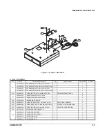
Page 23: ...Location Serviceable Remark A 1 JK70 10406A IPR HOUSING DRAWER 1 N A 2 JK72 40375B PMO COVER BOTTOM 1 Y A 3 6021 000225 NUT HEXAGON 2C M6 ZPC YEL SM20C 2 Y A 4 6031 000243 WASHER PLAIN M5 ID5 3 OD10...

Page 24: ..._COIN PARTITION B TYPE HIPS IVR HB 3 Y B 11 JK70 10307A IPR PLATE HOLDER B TYPE SBHG 1 T1 1 Y B 12 6002 000193 SCREW TAPPING RH 2S M3 L6 NI PLT SM20C 3 Y B 13 6002 001078 SCREW TAPPING PWH B M3 L5 ZPC...

Page 25: ...5 Exploded View and Parts List 5 10 SAM4S ER 150 Memo...

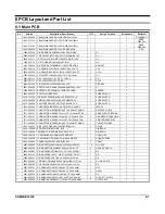
Page 26: ...1 SLIDE SWITCH Y 3601 000246 FUSE CARTRIDGE 250V 2A TIME LAG GLASS 5 1 250V 2A Y 3711 000034 CONNECTOR HEADER BOX 2P 1R 2 5mm STRAIGH 1 BATTERY 2P BLK Y 3711 000131 CONNECTOR HEADER 1WALL 11P 1R 2 5m...

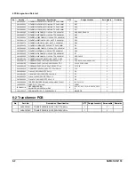
Page 27: ...TP 2 4X6 4MM 1 R7 Y 2001 000906 R CARBON 62KOHM 5 1 4W AA TP 2 4X6 4MM 3 R5 R18 R19 Y 2001 001144 R CARBON S 4 7KOHM 5 1 2W AA TP 2 4X6 1 R10 Y 2201 000119 C CERAMIC DISC 100nF 80 20 50V Y5V TP 7 C3...

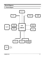
Page 28: ...agram 7 1 Block Diagram CPU SEM100 POWER FAIL MODE KEY DRAWER DISPLAY 9 Digit VFD RESET CURRENT DRIVER SIGNAL DETECTOR CRYSTAL OSCILLATOR 4MHZ BUZZER TURRET 9 Digit VFD Optional PRINTER M 42 lll KEY B...

Page 29: ...drawer driving circuit and the input voltages of the other different power sources The AC 5 6V is rectified by the Bridge diode rectifier 2KBP02 and it is regulated by the Capacitor 4700uF 7 2 A b VPR...

Page 30: ...SAM4S ER 150 8 1 8 Wiring Diagram 8 1 Main PCB CASH DRAWER TRANSFORMER FULLY WINDING MOTOR PRINTER BATTERY Key Board Matrix Part Electronic Circuit Part BROWN BLACK BLACK WHITE YELLOW BLACK...

Page 31: ...8 Wiring Diagram 8 2 SAM4S ER 150 Memo...

Page 32: ...M D 5 VF1 VLG C 11 100nF VLG VD SP R 10 4 7K 1 2W 13 12 74LS14 U 2 F 7 5K R 17 FG 97D 6 Fr ont 9 D i gi t 5 6K R 20 10K R 8 1N 4148 D 17 51K R 7 47K R 25 R 24 10K KEY B D R 26 2K VLG M O D E PO W ER T...

Page 33: ...9 Schematic Diagrams 9 2 SAM4S ER 150 MEMO...

Page 34: ...to record any special servicing information such as Service Bulletins or Supplements When possible record changes to Code numbers directly on the actual Parts List Always records Service Bulletin num...

Page 35: ......

Page 36: ...Shin Heung Precision March 2004 Printed in KOREA V1 0 Code No JK68 60959A...

Reviews: