7 Special Circuit Descriptions
7-2
SAM4S ER-5200 Series
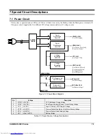
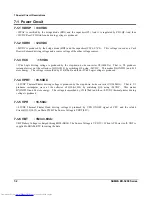
7-1 Power Circuit
7-1-1 VDISP : +30VDC
+30VAC is rectified by the bridge diode (BD1) and the capacitors(C9). And it is regulated by ZD1,Q8. And then
+30VDC Rear VFD Grid/Anode driving voltage is produced.
7-1-2 VDRV : +24VDC
+24VDC is produced by the bridge diode (BD2) and the capacitors(C5,C6,C7,C8). This voltage is used as a Cash
Drawer Solenoid driving voltage and a source voltage of the other voltage sources.
7-1-3
VCC :
+5VDC
+5Vdc Logic driving voltage is produced by the step-down dc-dc converter U2(34063A). That is, U2 produces
rectangular wave at the collector of Q9(A1010) by switching Q9 using +24VDC. This makes D6(IN5822) and L10
store energy. The voltage is smoothed by C14(470uF) and then +5Vdc Logic voltage is produced .
7-1-4 VPRT : +8.5VDC
+8.5VDC Thermal Printer driving voltage is produced by the step-down dc-dc converter U1(34063A). That is, U1
produces rectangular wave at the collector of Q10(A1010) by switching Q10 using +24VDC. This makes
D7(IN5822) and L8 store energy. The voltage is smoothed by C13(470uF) and then +8.5VDC thermal printer driving
voltage is produced .
7-1-5
VPH
:
+8.5Vdc
+8.5VDC Thermal Printer Head driving voltage is produced by VPH_ONOFF signal of CPU and the related
Circuit(Q13,Q14,15) on Main PWB. The Source Voltage is VPRT
(8.5V).
7-1-6 VBT : +Min 3.6Vdc
VBT Battery Voltage is charged through D28(SK14). The Source Voltage is VCC(5V). When AC Power is off, VBT is
supplied to SRAM, RTC for saving the data.
Downloaded from
www.Manualslib.com
manuals search engine


