background image

8 Trouble Shooting 

SAM4S ER-650 SERIES 


8-3


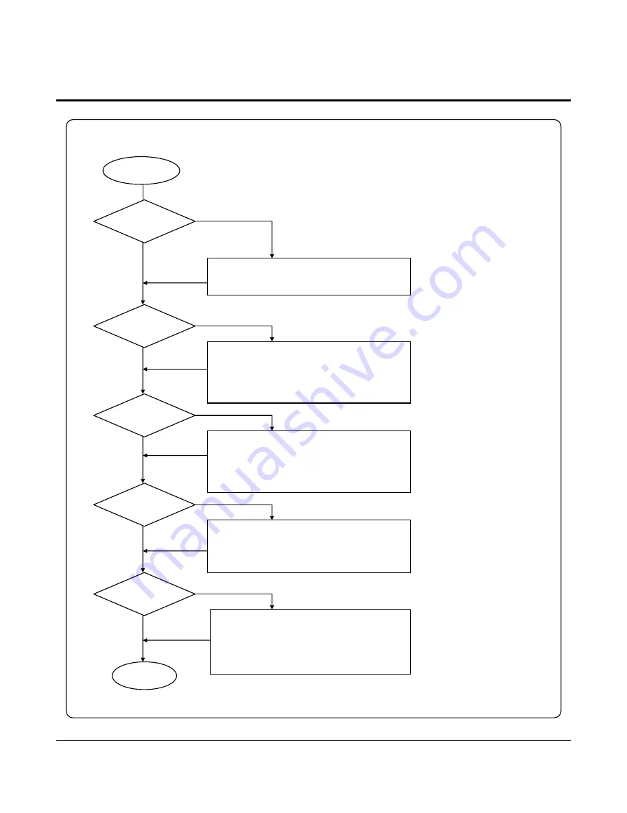
8-3 LCD Display Problem 

        End 

   LCD Problem 

 Reset Signal   
       Ok?  

 Y 

 N 

1. Refer to the Reset Part of System  Problem 
2. Check the Harness 

 Data Signal 
       Ok? 

 Control Line 
       Ok?  

 Y 

1. Check the CPU F_LCD_CS1 (P1.0) 
2. Check the CPU F_LCD_CS2 (P1.1) 
3. Check the CPU LCD_RW (P7.4) 
4. Check the LCD_DI (P8.2) 

1. Check the Harness 
2. Check the 74HC245 (U22) 
3. Check the HC138 (U7) & LCD_CS Signal 
4. Check the CPU /RD Signal 

 N 

 N 

  Back Light 
       Ok?  

 Y 

 Y 

1. Check the CPU INTP1 (P8.3) 
2. Check the TR A473, 2222 (14,16) 
3. Check the LF33CV (U27) 

 N 

   Contrast 
       Ok?  

 Y 

1. Check the VR1(10K) 
2. Check the LCD Output VO 
3. Check the Harness  
4. Check & Replace the LCD Module 

 N 

All manuals and user guides at all-guides.com

Summary of Contents for ER-650

Page 1: ...roduct Specifications 3 Installation and Operation 4 Assembly and Disassembly 5 Maintenance Adjustment 6 Exploded View and Part List 7 PBA Layout and Part List 8 Trouble Shooting 9 Block diagram 10 Wi...

Page 2: ...All manuals and user guides at all guides com...

Page 3: ...ithout prior notice Therefore you must check the correspondence of your manual with your machine No part of this manual may be copied or reproduced in any form or by any means without the prior writte...

Page 4: ...er Notes Notes may appear anywhere in the manual They describe additional information about the item Precaution symbols Indicates a Safety Precaution that applies to this part component Indicates the...

Page 5: ...part be copied photocopied reproduced translated or converted to any electronic or machine readable from without prior written permission of Shin Heung Precision SAM4S ER 650 R SERIES Service Manual...

Page 6: ...voltage supplies Always inspect for pinched out of place or frayed wiring Do not change the spacing between comp onents and the printed circuit board Check the AC power cord for damage Make sure that...

Page 7: ...d to the instrument chassis ground before connecting the positive lead always remove the instrument s ground lead last 1 3 Precautions for Electrostatic Sensitive Devices ESDs 1 Some semiconductor sol...

Page 8: ...ol XON XOFF S W Flow Control Baud Rate 4800 9600 19200 Bps Connector DB9P Female I F PBA RS 232C 1 RS 232C 2 Interface Serial IRC Flow Control XON XOFF S W Flow Control Baud Rate 9600 Bps Connector Mo...

Page 9: ...2 Product Specifications 2 2 SAM4S ER 650 SERIES 282 7 400 450 2 2 Appearance 2 2 A Appearance Dimensions mm Figure2 1 Dimensions All manuals and user guides at all guides com...

Page 10: ...2 Product Specifications SAM4S ER 650 SERIES 2 3 2 2 B Feature Locations Figure2 2 Feature Locations All manuals and user guides at all guides com...

Page 11: ...mm s At 8 5V of Motor Terminal Voltage Power Voltage 8V 8 5V Recommend Head Motor Power Supply Volt Circuit input Voltage 5V Head Control Sensor Heat Element Density 8 Dots mm 0 125 mm Dot Total Head...

Page 12: ...Printable Area The Printable area of a paper with width of 80 1 0mm 3 13 0 02 is 72 2 0 2mm 2 84 0 008 512 dots and the space on the right and left sides are approximately 3 7mm 0 146 Figure2 3 Printa...

Page 13: ...m 0 125 mm Dot Typical Resistance Value 176 4 Printer Head Current Approx 3 1 A Constant B 3950K 2 Resistance Value 30 5 25 Temperature Character Rt R 25 Exp B 1 T 273 1 25 273 Thermister Operating Te...

Page 14: ...se A 4 Phase A_ 2 3 F c Paper End Sensor Pin Assignments Pin No Signal Description Remark 1 GND 2 Paper End Signal 3 VCC 2 3 F d Thermal Head Connector Pin Assignments Pin No Signal Description Remark...

Page 15: ...t Voltage Current U S A AC 120V 150mA 60Hz Min 90V Max 132V Europe AC 230V 80mA 50Hz Min 198V Max 264V Power Consumption Stand By 10W Operating 15W Output Voltage AC 19V 2 3A Wire Color Blue Blue AC 2...

Page 16: ...ord Length 7 Bit 8 Bit Parity None Even Odd Connector DB9P Female I F PBA Side Voltage Supply VCC 5V 200mA is supplied at 9Pin of D SUB Connector For Bar Code Reader or other devices Table2 18 RS 232C...

Page 17: ...M1 and COM2 Power Consumption If the Total Power Consumption of the attached devices is exceeded the specification 200mA the system cut the VCC of D SUB Connector Then the attached devices do not work...

Page 18: ...Data Word Length 7 Bit 8 Bit Parity None Even Odd Connector Modular Jack Connector 12P 2Port 6Pin Table2 20 IRC Specification 2 5 B b IRC I F Cable Figure2 6 IRC Cable 2 5 B c Cable Connection Figure2...

Page 19: ...In Out Transmit Receive Data Line B Pin 1 and Pin 2 are shorted each other on I F PBA 3 9 F GND 4 10 F GND Frame Ground 5 11 TX RX_A In Out 6 12 TX RX_A In Out Transmit Receive Data Line A Pin 4 and P...

Page 20: ...SAM4S ER 650 SERIES 3 1 3 Installation and Operation 3 1 System Configuration 3 1 A Configuration Figure3 1 System Configuration All manuals and user guides at all guides com...

Page 21: ...the roll into the concave bottom of the printer And put the leading edge of the paper over the printer 4 Close the printer cover slowly until it locks firmly Tear off the excess paper 3 2 B RS 232C S...

Page 22: ...ial Cable to other ECR 3 2 D Options No Item Description Remark 1 RS 232 IRC I F Board I F PBA 2 Clerk Key 5EA 10EA 15EA Selectable Table 3 1 Option 3 2 E Supplies No Item Description Remark 1 Paper R...

Page 23: ...e for normal registrations X X Use to read register reports and perform other manager functions Z Z Use to read register reports and reset totals to zero PGM P Use to program the register SM C Use for...

Page 24: ...ure after the cash register is programmed it causes all programs and totals to be erased and to be default 1 Turn off the power switch 2 Turn the Mode key marked C to Service Mode position 3 Press and...

Page 25: ...key on key board 2 Then the buzzer will work for 1 sec 3 After testing the buzzer Some characters are displayed on the rear VFD display 4 After testing the rear VFD display the LCD display tests The...

Page 26: ...st RS232C 1 Install the serial loop back test jig Short pin 2 3 and pin 4 6 of DSUB connector 2 Press 4 key on key board 3 Press 0 key on the key board 0 Loop Back Test for RS232 Port 1 If error occur...

Page 27: ...3 Installation and Operation 3 8 SAM4S ER 650 SERIES Memo All manuals and user guides at all guides com...

Page 28: ...and VFD Display Block 1 Remove the two screws B 24 Page 6 3 2 Remove the Window Holder B 23 Page 6 3 3 Separate the LCD Display parts B 1 6 B 20 from the Case Upper Ass y B Page 6 3 4 Separate the VFD...

Page 29: ...e core and the number of turn refer to the Serial I F part of chapter specification Note To Install Reverse the removal procedure 4 2 C Power Transformer and Power PBA 1 Separate the two harnesses j p...

Page 30: ...paper supplier with pushing the blue cap lever 4 Clean the Printer Head Thermal Element with a cotton swab moistened with alcohol solvent ethanol methanol IPA 5 After confirming that alcohol solvent h...

Page 31: ...st the view angle of the Operator LCD Display Figure5 2 Adjustment of the View Angle 5 2 B LCD Display Contrast You can adjust the contrast of the Operator LCD Display by using the VR on the left side...

Page 32: ...SAM4S ER 650 SERIES 6 1 6 Exploded View and Part List Figure6 1 Total Disassembly ER 650 ER 650R All manuals and user guides at all guides com...

Page 33: ...R PRINTER A ASS Y COVER PRINTER No Parts No Description Specification Q ty Design Location Serviceable Remark JK97 10008A MEA HOU COVER PRINTER ER 650R STD 1 Y JK70 10320A IPR CUTTER PAPER 1 N A JK72...

Page 34: ...6 Exploded View and Part List SAM4S ER 650 SERIES 6 3 Figure6 3 ASS Y CASE UPPER All manuals and user guides at all guides com...

Page 35: ...EL 2 B MODE CLERK Y B 10 JK39 40508A CBF HARNESS UL1015 350mm 1 Y B 11 6002 000319 SCREW TAPPING PH 2 M3 L8 ZPC YEL 2 B MODE ROTARY Y B 12 6002 000319 SCREW TAPPING PH 2 M3 L8 ZPC YEL 3 B MODE C MODE...

Page 36: ...6 Exploded View and Part List SAM4S ER 650 SERIES 6 5 Figure6 4 ASS Y PRINTER STM 210 All manuals and user guides at all guides com a l l g u i d e s c o m...

Page 37: ...6 Exploded View and Part List 6 6 SAM4S ER 650 SERIES Figure6 5 Lubrication Points of the Printer STM 210 All manuals and user guides at all guides com...

Page 38: ...2 M3 L10 ZPC 1 Y C 17 JK70 50009A SCREW MACHINE RH 2 M2 L4 WHITE 2 Y C 18 JK72 20005A PMO SIDE COVER POM BLK 1 Y C 19 JK72 20007A PMO GEAR REDUCTION 17_39 POM 1 Y C 20 JK72 20008A PMO GEAR REDUCTION...

Page 39: ...CHINE PWH 2 M3 L4 ZPC 2 Y ONLY SAC 60 C 46 JK39 40021A CBF HARNESS UL1015 330 130 GRN 1 Y C 47 JK96 01231B ELA P END SENSOR STM 220 1 Y C 48 JK96 10141A ELA PARTITION ASS Y STM 220 1 Y STM 220 JK72 20...

Page 40: ...ble it from the PRINTER 2 Open the COVER TOP 3 Disassemble the TPH assembly by pulling the lower part of TPH assembly and lift it up 4 Assemble the TPH assembly in reverse order and close the COVER TO...

Page 41: ...6 Exploded View and Part List 6 10 SAM4S ER 650 SERIES Figure6 7 ASS Y KEYBOARD FLAT Figure6 8 ASS Y KEYBOARD RAISED All manuals and user guides at all guides com a l l g u i d e s c o m...

Page 42: ...UNIT KEYBOARD FRENCH Y D JK59 30002D UNIT KEYBOARD SPANISH Y D 1 JK72 20010A PMO BLANK KEY TOP 1 6 POM IVORY 1 Y D 2 JK81 10946A AS KEY CAP L 1X2 2 Y D 3 LABEL KEY TOP SET ER 650R 1 N D 4 JK81 10286B...

Page 43: ...6 Exploded View and Part List 6 12 SAM4S ER 650 SERIES Figure9 6 ASS Y CASE LOWER All manuals and user guides at all guides com...

Page 44: ...Y E 9 6006 000199 SCREW ASS Y TAPT WT BH M4 L8 ZPC 1 Y E 10 6002 000174 SCREW TAPPING PWH 2 M3 L10 ZPC 4 Y E 11 JK70 00049A IPR GROUND PLATE SECC T0 8 1 Y E 12 JK92 01223A PBA MAIN BOARD ER 650R BASIC...

Page 45: ...b12 b5 b3 b4 b7 b8 b6 b9 c ASS Y HOUSING e ASS Y BOTTOM d ASS Y LOCK b ASS Y TRAY TILL b10 e1 e5 e2 e3 e4 e7 e6 e8 d1 d2 d3 d4 d11 d6 d7 d9 d10 d5 d8 c2 c1 c3 a8 a4 a5 a3 a2 a6 a7 a1 a ASS Y BILL COIN...

Page 46: ...TAPPING PWH 2 M3 L8 ZPC YEL 3 Y a 2 JK70 00068A IPR HOLDER PLATE A TYPE SBHG 1 T1 2 1 Y a 3 JK72 00083A PMO BILL PARTITION A TYPE HIPS BLK 5 Y a 4 JK72 00082A PMO BILL TILL A TYPE HIPS BLK 2 Y a 5 JK...

Page 47: ...K LEVER A TYPE 2 LATCH SHORT LEVER 1 N d 5 6107 001014 SPRING ES 0 4 D4 8 L18 1 Y d 6 JK33 10500A SOLENOID DC A DRAWER 1 Y d 7 6001 000131 SCREW MACHINE BH 2 M3 L6 ZPC YEL 2 Y d 8 6001 000525 SCREW MA...

Page 48: ...SAM4S ER 650 SERIES 7 1 7 PBA Layout and Part List 7 1 Main PBA All manuals and user guides at all guides com...

Page 49: ...01001 R WIRE WOUND 0 1ohm 5 1W AA TP 3 3x9mm 2 R4 R5 Y 2101 001023 VR ROTARY 10Kohm 30 0 03W BUTTOM 1 VR1 Y 2301 000010 C FILM PEF 100nF 5 100V TP 11 5x12 5mm 1 C11 Y 2401 000032 C AL 100uF 20 50V GP...

Page 50: ...IODE RECTIFIER M4 400V 1A SMD 2 TP 2 D1 D4 Y 0404 001051 DIODE SCHOTTKY SK14 40V 1000MA DO 214AA 2 D11 D29 Y 0501 000457 TR SMALL SIGNAL MMBT2222A NPN 350MW SOT 8 Q13 Q9 Q15 Q14 Q20 Q8 Q10 Q1 Y 2007 0...

Page 51: ...P 2012 4 C36 C40 C57 C74 N 2203 000634 C CERAMIC CHIP 0 022nF 5 50V NP0 TP 201 3 C27 C32 C33 N 2203 000748 C CERAMIC CHIP 0 03nF 5 50V NP0 TP 2012 13 C35 C37 C58 C41 C49 C50 C52 C54 C59 C42 C43 C9 C56...

Page 52: ...BK 2 V1 2 Y 2201 000023 C CERAMIC DISC 2 2nF 20 125V 1 C4 5 Y 2305 001021 C FILM MPEF 100nF 20 275V TP 1 C2 Y 3601 000246 FUSE FERRULE 250V 2A TL GLASS 1 FU1 Y 3602 000001 FUSE CLIP 30mohm 2 FU1 Y 37...

Page 53: ...O 92 2 Q2 Q3 Y 1006 000133 IC DRIVER RECEIVER 232 SOP 16P 150MIL DU 2 U2 U3 Y 2203 000192 C CERAMIC CHIP 100nF 80 20 50V Y5V TP 2 C4 C6 N C7 C10 C11 C12 C16 C1 2203 000938 C CERAMIC CHIP 0 47nF 5 50V...

Page 54: ...n Serviceable Remarks JK92 00970A PBA SUB 650 TURRET ER 650 BASIC 1 ER 650 Y 0402 000129 DIODE RECTIFIER 1N4003 200V 1A 1 D1 Y 0402 000208 DIODE RECTIFIER EK 04 40V 1 5A DO 41 1 D2 Y 2202 000579 C CER...

Page 55: ...000457 TR SMALL SIGNAL MMBT2222A NPN 350MW SOT 1 Q1 Y JK41 10531B PCB FISCAL ER 5240F FR 4 2L T1 6mm 348X5 1 N Memory Size 2MBITs No Part No Description Specification Q TY Design Location Serviceabl...

Page 56: ...7 PBA Layout and Part List SAM4S ER 650 SERIES 7 9 MEMO All manuals and user guides at all guides com a l l g u i d e s c o m...

Page 57: ...se FU1 2 Check the Bridge Diode BD2 1 Check the Bridge Diode BD1 2 Check the Zenner Diode ZD1 3 Check the TR Q1 N N Power VCC 5V Ok Power VPH 8 5V OK Y Y 1 Check the IC34063 U1 2 Check the TR1010 708...

Page 58: ...Ok Program Ok Y 1 Check the Addr Data line Pattern 2 Check Change the EP ROM 1 Check the LM393 U12 2 Check the Power 24V 5V 3 Check the Pattern on PCB N N SRAM Ok Y Y 1 Check the CS Decoder HC138 U2...

Page 59: ...e CPU F_LCD_CS2 P1 1 3 Check the CPU LCD_RW P7 4 4 Check the LCD_DI P8 2 1 Check the Harness 2 Check the 74HC245 U22 3 Check the HC138 U7 LCD_CS Signal 4 Check the CPU RD Signal N N Back Light Ok Y Y...

Page 60: ...2 Check the Harness Connector Ok Power VDI VCC Ok Y 1 Refer to the Power Problem 2 Check the Harness 1 Check the Harness 2 Check the CPU Disconnection Function Pin P10 7 N N VFD PBA Assy Ok Y Y 1 Che...

Page 61: ...rcuit and Pattern Power Vcc VH Ok Y 1 Refer to the Power Problem 2 Check the Harness N Sensor OK 1 Check the related Circuit and Pattern IC LM393 2 Check the Harness 3 Check the Sensor PBA Y Feed Moto...

Page 62: ...T541 Data Line 4 Check the related circuit 5 Check Change Key Board Ass y 6 Check the KBD Connector on PBA Specific Key Failure 1 Check the affected Key 2 Check the Matrix Bus Data Bus 3 Check the Dio...

Page 63: ...4 P8 7 3 Check the related circuit Component D288 Q4 Q5 4 Check the Solenoid in the Drawer Compulsory Failure 1 Check the Compulsory Harness Connector 2 Check the micro switch in the Drawer N Y End E...

Page 64: ...Pin on CPU 4 Check the MAX232 Driving Chip and related Circuit on I F PBA Communication Failure 1 Check the connection of the RS 232C Connector and Other side 2 Check the I F Cable whether it is open...

Page 65: ...g the Loop Back test Connector 2 Check the Tx Rx Pin on I F PBA 3 Check the 75176 Driving Chip and related Circuit on I F PBA Communication Failure 1 Check the connection of the IRC Connector and Othe...

Page 66: ...8 Trouble Shooting 8 10 SAM4S ER 650 SERIES Memo All manuals and user guides at all guides com a l l g u i d e s c o m...

Page 67: ...CIRCUIT RS 232 DRIVER 1 2 RS 232C CONNECTOR 1 2 IRC DRIVER IRC CONNECTOR FRONT LCD DRIVER FORNR LCD REAR VFD DRIVER REAR VFD KEY BOARD DRIVER KEY BOARD MODE KEY DRIVER MODE KEY CLERK KEY DRIVER CLERK...

Page 68: ...9 Block Diagram 9 2 SAM4S ER 650 SERIES Memo All manuals and user guides at all guides com...

Page 69: ..._LCD_CS1 D7 D6 D5 D4 D3 D2 10 VOUT VR1 8 7 6 5 4 3 2 1 8 7 6 5 4 3 2 1 D1 D0 CS E LCD_RW RW LCD_DI DI VO VR1 VO VCC GND 2 1 2 1 Back Light Voltage GND 8 7 6 5 4 3 2 1 8 7 6 5 4 3 2 1 Disconnect Check...

Page 70: ...10 Wiring Diagram 10 2 SAM4S ER 650 SERIES Memo All manuals and user guides at all guides com...

Page 71: ...r Block 11 4 4 Fiscal Block 11 5 5 Power Block 11 6 6 Rear Display Drawer Block 11 7 7 Key Scan Block 11 8 8 LCD Display Block 11 9 9 Printer Block 11 10 10 Printer Connection Block 11 11 2 Interface...

Page 72: ...4 7456MHz OSC1 R56 4 7K D VCC 4 C48 47nF 1 1A 3 3A 4 4A 2 2A 5 5A M51953B U4 C46 100nF R37 2 2K 3 REF 6 VO 1 XIN 8 VCC 2 XOUT 7 VI 4 LF 5 GND FS741 U1 14 VSS2 12 RESET 8 BYTE 9 CNVSS 15 XIN 13 XOUT 62...

Page 73: ...SAM4S ER 650 SERIES 11 3 11 2 MEMORY PART All manuals and user guides at all guides com...

Page 74: ..._COMP1 2 1 DWR_COMP2 5 2 DTR1 VCC 5 2 4 1 VCC DSR2 TXD2 VCC CLERK2 COVER_OPEN 3 Clerk Key 8 10 7 4 Date A3 D 2006 05 09 Drawn by L4 3 2 1 Q4 KSD288 Y DISCLK L6 3 2 1 Q5 KSD288 Y Rear Display VFD L3 L1...

Page 75: ...SAM4S ER 650 SERIES 11 5 11 4 FISCAL PART All manuals and user guides at all guides com...

Page 76: ...11 6 SAM4S ER 650 SERIES 11 5 POWER PART Y Y All manuals and user guides at all guides com a l l g u i d e s c o m...

Page 77: ...SAM4S ER 650 SERIES 11 7 11 6 DRAWER DISPLAY VFD PART G G All manuals and user guides at all guides com...

Page 78: ...11 8 SAM4S ER 650 SERIES 11 7 KEY SCAN PART Y All manuals and user guides at all guides com...

Page 79: ...SAM4S ER 650 SERIES 11 9 11 8 LCD DISPLAY PART All manuals and user guides at all guides com...

Page 80: ...11 10 SAM4S ER 650 SERIES 11 9 PRINTER PART G G All manuals and user guides at all guides com...

Page 81: ...SAM4S ER 650 SERIES 11 11 11 10 PRINTER CONNECTION PART All manuals and user guides at all guides com a l l g u i d e s c o m...

Page 82: ...3 CN1 C FGND 1N4735A ZD4 FGND 4 D ER 650 IF SCH Sheet 1 C17 1uF 50V 470pF C16 L18 L20 4 CN4 D 1 CN4 A 6 CN4 F CON BOX 6P 2 5MM ST VCC SMDC050 U4 4 7K R4 C14 1uF 50V 2 CN2 B L3 L7 8 CN2 H 5 CN2 E 10 C...

Page 83: ...C 8 C N 1 H 5 C N 1 E 6 C N 1 F 2 C N 1 B 3 C N 1 C VFD _STO R BE VFD _LATC H VFD _SC LK VFD _SD I N ER 650 5500 D I SPLAY 7 C N 1 G 4 C N 1 D 1 C N 1 A C O N BO X 8P 2 5M M ST 100nF C 2 VC C VFD R EA...

Page 84: ...14 VC C A16 A13 A7 A4 A1 A10 VC C JP2 0 2002 12 28 D 1 D 4 D 7 V1 1 KSH C KW VC C JP1 0 4 7K R 5 R 10 R 9 0 R 3 A 0 16 D 0 7 C E 4 7K R 1 VC C 100nF AXI AL C 1 512K 1M 2M FI SC AL PC B VC C R 2 560 2...

Page 85: ...al servicing information such as Service Bulletins or Supplements When possible record changes to Code numbers directly on the actual Parts List Always records Service Bulletin numbers and Application...

Page 86: ...All manuals and user guides at all guides com a l l g u i d e s c o m...

Page 87: ...Shin Heung Precision July 2007 Printed in KOREA V2 0 Code No JK68 00061B All manuals and user guides at all guides com...

Reviews: