background image

2 Product Specifications 

SAM4S ER-900/SPS-300 SERIES                                                                2-13


2-5 Interface Specifications 

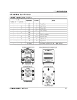
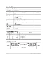
2-5-7 LAN (IRC) Signal Description 

Pin No 

Signal Name 

Signal Direction 

Function 

ENET TX+ 

OUT 

Ethernet Transmit Data Line(+) 

ENET TX- 

OUT 

Ethernet Transmit Data Line(-) 

ENET RX+ 

IN 

Ethernet Receive Data Line(+) 

4 N.C 


5 N.C 


ENET RX- 

IN 

Ethernet Receive Data Line(+) 

7 N.C 


8 N.C 


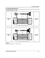
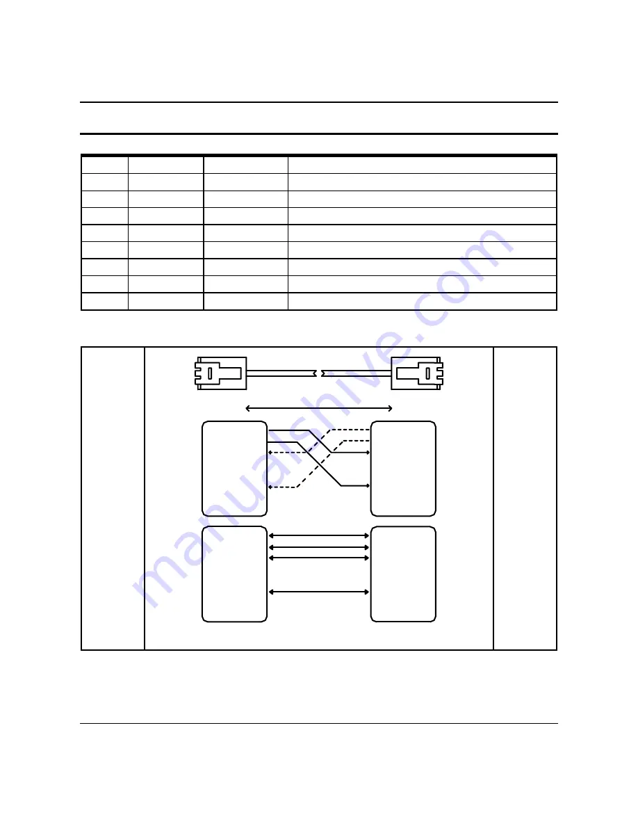
2-5-8 LAN (IRC) Interface Cable 

SPS-300 

/ER-900 SIDE 


MAX 100M


5(N.C)

7(N.C)
8(N.C)

4(N.C)

5(N.C)

6(ENET RX-)

7(N.C)

1(ENET TX+)
2(ENET TX-)
3(ENET RX+)

6(ENET RX-)

1(ENET TX+)
2(ENET TX-)
3(ENET RX+)

4(N.C)

8(N.C)


( ECR to ECR IRC I/F CABLE )


7(N.C)
8(N.C)

6(ENET RX-)

7(N.C)

2(ENET TX-)
3(ENET RX+)

4(N.C)

6(ENET RX-)

4(N.C)

2(ENET TX-)
3(ENET RX+)

5(N.C)

1(ENET TX+)

8(N.C)

5(N.C)

1(ENET TX+)


(ECR to HUB IRC I/F CABLE) 


USER SIDE 


Summary of Contents for ER-900 Series

Page 1: ...ER Manual 1 Precaution Statements 2 Product Specifications 3 Installation and Operation 4 Disassembly and Assembly 5 Maintenance and Adjustment 6 Troubleshooting 7 Exploded Views and Parts List 8 PCB Layout and Parts List 9 Wiring Diagram 10 Bock Diagram 11 Schematic Diagrams SERVICE ...

Page 2: ... prior notice Therefore you must check the correspondence of your manual with your machine No part of this manual may be copied or reproduced in any form or by any means without the prior written consent of Shin Heung Precision Note Before using this ECR system for the first time leave it powered on in the REG mode for at least twenty four hours This allows the Lithium battery which maintains the ...

Page 3: ...00 SPS 300 SERIES Notes Notes may appear anywhere in the manual They describe additional information about the item Precaution symbols Indicates a Safety Precaution that applies to this part component Indicates the part or component is an electro statically sensitive device Use caution when handling these parts ...

Page 4: ...ed This manual may not in whole or in part be copied photocopied reproduced translated or converted to any electronic or machine readable from without prior written permission of Shin Heung Precision SAM4S ER 900 SPS 300 SERIES July 2011 V1 0 Printed in KOREA ...

Page 5: ...sharp edges and especially the AC and high voltage supplies Always inspect for pinched out of place or frayed wiring Do not change the spacing between components and the printed circuit board Check the AC power cord for damage Make sure that leads and components do not touch thermally hot parts 7 Product Safety Notice Some electrical and mechanical parts have special safety related characteristics...

Page 6: ...nstrument s ground lead to the instrument chassis ground before connecting the positive lead always remove the instrument s ground lead last 1 3 Precautions for Electrostatically Sensitive Devices ESDs 1 Some semiconductor solid state devices are easily damaged by static electricity Such components are called Electrostatically Sensitive Devices ESDs examples include integrated circuits and some fi...

Page 7: ...232C 1 DSUB 9 RS 232C 2 DSUB 9 RS 232C 3 RJ45 RS 232C 4 RJ45 Option RS 232C 3 4 LAN 10 100 base T ETHERNET 16REG_MAX SD CARD 1 Slot option MSR 1 Slot option DRAWER 2 PORT Default internal 1 Option RJ 11 2 i BUTTON Addmat Magnetic Option USB 1 Port Device Option Printer Model LTPD245 CAPD245 SII Printing Speed 85mm Sec Detail Spec refer to Next Page Auto Cutter Type Guillotine Cutting Method 1 Poin...

Page 8: ...ge Supply VCC 5V 1A supplies at RS 232C 1 4 RS 232C 1 DSUB 9 RS 232C 2 DSUB 9 RS 232C 3 RJ45 RS 232C 4 RJ45 Option RS 232C 3 4 SD CARD 1 Slot option MSR 1 Slot option DRAWER 2 PORT Default internal 1 Option RJ 11 2 i BUTTON Addmat Magnetic Option USB 1 Port Device Option Printer Model LTPD245 CAPD245 SII Printing Speed 85mm Sec Detail Spec refer to Next Page Auto Cutter Type Guillotine Cutting Met...

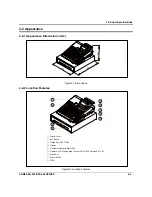
Page 9: ...Appearance 2 2 1 Appearance Dimensions mm Figure2 1 Dimensions 2 2 2 Location Features Figure2 2 Location Features Printer Cover Key Board Dallas Key i BUTTON Drawer Customer Display 9 Digit LED Operator LCD Display 2line 16char LCD or 192X 64 Graphic LCD Mode Key Power Switch MSR ...

Page 10: ...5 mm Sec Power Voltage 6 5V 9 0V Head Motor Power Supply Volt Circuit Input Voltage 3 3V Head Control Sensor Heat Element Density 8 Dots mm 200dpi Total Head Elements 384 Dots Dot Line Available Printing Width 48 mm Printer Head Heat Element Typical Ω 173 Ω 3 Line Feed Motor 1 2Phase Bi Polar Stepping Motor Head Temperature Thermistor Paper End Sensor Reflecting Photo Sensor Printer Cover Open Sen...

Page 11: ...per Mfg Co Ltd KT55F20 Papier fabric August KoehlerAG 2 3 3 Printable Area The Printable area of a paper with width of 58 0 0 1mm is 48mm 384 dots and the space on the right and left sides are approximately 4 75mm Figure2 3 Printable Area 2 3 4 Character Specification Item Description Remark Character Structure 12 W 24 H Font Including a Horizontal Character Size 1 25 mm W 3 0 mm H Column Pitch 1 ...

Page 12: ...Paper Feeding Minimum Feed Pitch 0 0625 mm Paper Feeding Feeding Speed 85 mm Sec Power Voltage 6 5V 9 0V Power Supply Volt Power Supply Volt Circuit Input Voltage 3 3V Heat Element Density 8 Dots mm 200dpi Printer Head Total Head Elements 384 Dots Dot Line Available Printing Width 48 mm Printer Head Heat Element Typical Ω 173 Ω 3 Line Feed Motor 1 2Phase Bi Polar Stepping Motor Head Temperature Th...

Page 13: ...paper Mfg Co Ltd KT55F20 Papier fabric August KoehlerAG 2 3 3 Printable Area The Printable area of a paper with width of 57 5mm is 48mm 384 dots and the space on the right and left sides are approximately 4 75mm Figure2 4 Printable Area 2 3 4 Character Specification Item Description Remark Character Structure 12 W 24 H Font Including a Horizontal Character Size 1 25 mm W 3 0 mm H Column Pitch 1 5 ...

Page 14: ...smission Serial Data Transmission Synchronization Asynchronous Hand Shaking Flow Control H W DTR DSR S W XON XOFF XON ASC Code 11h XOFF ASC Code 13h Signal Level Logic 1 MARK 3V 15V Logic 0 SPACE 3V 15V Baud Rate 2400 9600 19200 38400 57600 115200 bps Default 9600 bps Data Word Length 7 Bit 8 Bit Parity None Even Odd Connector DSUB9P Male COM 1 COM 2 RJ 45 Modular Jack COM 3 COM 4 Option RS 232C 3...

Page 15: ...PIN NO DSUB9 CN1 RJ45 CN3 Signal Name Direction Function 1 DCD IN Carrier Detect 2 4 RXD IN Receive Data 3 3 TXD OUT Transmit Data 4 DTR OUT Data Set Ready 5 7 GND 6 DSR IN Data Terminal Ready 7 8 RTS OUT Request To Send 8 2 CTS IN Clear To Send RI IN Ring Indicator 9 1 5V 500mA Total Power 1A COM 1 2 Pin9 COM 3 4 Pin1 ...

Page 16: ...cations 2 5 3 RS 232C Interface Cable SPS 300 ER 900 SIDE DSUB9 FEMALE 5V COM1 COM2 I F CABLE PIN CONNECTION USER SIDE DSUB25 MALE SPS 300 ER 900 SIDE DSUB9 FEMALE 5V COM1 COM2 I F CABLE PIN CONNECTION USER SIDE DSUB9 MALE CAUTION COM 1 COM 2 supplies 5V to DSUB9 Pin Num 9 15m 15m ...

Page 17: ...TXD 7 S GND 2 DSR 7 RTS 8 CTS 5 S GND 3 TXD 4 DTR 8 DTR 4 RXD 6 DSR 2 RXD COM3 COM4 I F CABLE PIN CONNECTION USER SIDE DSUB9 MALE SPS 300 ER 900 SIDE RJ 45 5 RTS 7 S GND 8 DTR 3 TXD 4 RXD 4 RTS 7 S GND 6 DSR 2 TXD 3 RXD 6 CTS 2 DSR 5 CTS 20 DTR COM3 COM4 I F CABLE PIN CONNECTION USER SIDE DSUB25 MALE CAUTION COM 3 COM 4 supplies 5V to RJ45 Pin Num 1 15m 15m ...

Page 18: ...rential Common Mode Range 0 8 2 5 V Differential Receive Sensitivity 200 mV Single End Receive Threshold 0 8 2 5 V Speed 12Mbps Power Supply 5V 500mA For HID Cable Connector Cable 5m 2m Connector A type Support Spec USB Device 2 5 5 USB Signal Description Pin No Signal Name Color Function SHELL Shield Drain Wire Frame GND 1 VBUS Red Host Power DC5 V 500 mA 2 D White Differential Data Line 3 D Gree...

Page 19: ...thernet Receive Data Line 4 N C 5 N C 6 ENET RX IN Ethernet Receive Data Line 7 N C 8 N C 2 5 8 LAN IRC Interface Cable SPS 300 ER 900 SIDE MAX 100M 5 N C 7 N C 8 N C 4 N C 5 N C 6 ENET RX 7 N C 1 ENET TX 2 ENET TX 3 ENET RX 6 ENET RX 1 ENET TX 2 ENET TX 3 ENET RX 4 N C 8 N C ECR to ECR IRC I F CABLE 7 N C 8 N C 6 ENET RX 7 N C 2 ENET TX 3 ENET RX 4 N C 6 ENET RX 4 N C 2 ENET TX 3 ENET RX 5 N C 1 ...

Page 20: ...rawer Kick Out Driver Signal 3 DRACOMP IN Drawer Open Close Signal 4 24v Supply DC 24 V 5 DRAWER OUT OUT Drawer Kick Out Driver Signal 6 F G Frame GND CAUTION Make sure that installed 24V Cash Drawer Make sure that the Cash Drawer Solenoid Resistance is more than 20 Ohm 2 5 10 DRAWER Interface Cable SPS 300 ER 900 SIDE RJ11 6P COMPULSORY DRAWER DRAWER I F CABLE 6 1 DRAWER CONNECTOR USER SIDE ...

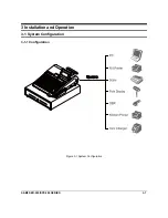
Page 21: ...SAM4S ER 900 SPS 300 SERIES 3 1 3 Installation and Operation 3 1 System Configuration 3 1 1 Configuration Figure 3 1 System Configuration ...

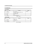
Page 22: ...y 5EA 10EA 15EA Selectable 2 Water Proof RAISED 63KEY RAISED 91 98 KEY Option FLAT 150KEY Default 3 Memory SRAM 4Mb or 16Mb 4 MSR 1Slot 5 Interface RS 232 2 RS 232 USB Table 3 1 Option 3 2 2 Supplies No Item Description Remark 1 Paper Roll 2 Station 2 EA 1 Station 1EA 2 Mode Key VD REG X Z P C 3 User Manual 1 EA Table 3 2 Supplies ...

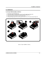
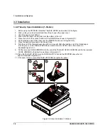
Page 23: ...Push up the green lever toward and then lift up to open the paper cover Fig 3 2 B 3 Ensure that the paper is being fed from the bottom of the roll Fig 3 2 C 4 Close the paper cover slowly until it locks firmly Fig 3 2 D 5 Passing the leading edge of the paper through the cutter slot Tear off the excess paper Fig 3 2 E Figure 3 2 Paper Installation 1 Station ...

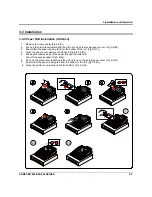
Page 24: ...e paper over the PRINTER as shown in Figure3 2 D 7 Close the paper cover slowly until it locks firmly 8 Fold the end of the thermal paper about 20mm in length Slide the leading end of the folded paper into the groove on the TAKE UP SPOOL and wind it onto the SPOOL two or three turns as illustrated Figure3 3 9 Put the removed GUIDE WINDING into the end of the TAKE UP SPOOL WINDING and fix the remov...

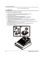
Page 25: ...hat the paper is being fed from the bottom of the roll Fig 3 4 C 4 Close the paper cover slowly until it locks firmly Fig 3 4 D 5 Passing the leading edge of the paper through the cutter slot Tear off the excess paper Fig 3 4 E 6 Push up the green lever toward and then lift up to open the journal paper cover Fig 3 4 F 7 Ensure that the paper is being fed from the bottom of the roll Fig 3 4 G 8 Clo...

Page 26: ...Figure3 4 G 6 Put the leading edge of the paper over the PRINTER as shown in Figure3 4 H 7 Close the paper cover slowly until it locks firmly 8 Fold the end of the thermal paper about 20mm in length Slide the leading end of the folded paper into the groove on the TAKE UP SPOOL and wind it onto the SPOOL two or three turns as illustrated Figure3 5 9 Put the removed GUIDE WINDING into the end of the...

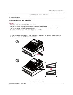
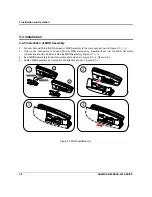
Page 27: ...r hand from being cut by the angle and the chassis Connect all the cables correctly When connecting or disconnecting the cables be careful not to apply stress to the cables It may cause disconnection Be careful not to bind interface cables and AC power cord together 1 Take off the area MSR assembly area shown in the Figure 3 6 1 by using a shaped screw driver 2 Figure 3 6 2 shows the difference be...

Page 28: ...t as shown in Figure 3 7 1 a 4 Tidy up the connectors of Ground Wire MSR Harness by inserting them into the MSR Assembly Connectors should be hidden inside the MSR Assembly Figure 3 7 1 b 5 Insert MSR Assembly into the main set bracket holes as in Figure 3 7 2 Figure 3 5 3 6 Tighten MSR Assembly by moving it to the direction shown in Figure 3 7 4 Figure 3 7 MSR Installation 2 ...

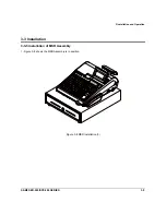
Page 29: ...3 Installation and Operation SAM4S ER 900 SPS 300 SERIES 3 9 3 3 Installation 3 3 5 Installation of MSR Assembly 1 Figure 3 8 shows the MSR Assembly is in position Figure 3 8 MSR Installation 3 ...

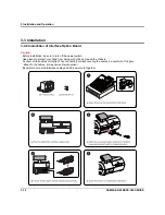
Page 30: ...installation be sure to turn off the power switch Use gloves to protect your hand from being cut by the angle and the chassis Connect all the cables correctly When connecting or disconnecting the cables be careful not to apply stress to the cables It may cause disconnection Be careful not to bind interface cables and AC power cord together ...

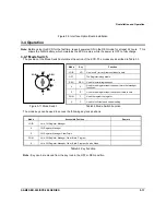
Page 31: ...ter is inoperable REG REG Used for normal registrations X X Used to read register reports and perform other manager functions Z Z Used to read register reports and reset totals to zero PGM P Used to program the register S C Used for H W tests and special setting Figure3 11 Mode Switch Table3 3 Mode Switch Function The mode keys can be used to access the following key lock positions Mode Accessible...

Page 32: ...ault 1 Turn off the power 2 Turn the control lock to the unmarked position one position clockwise from the PGM position 3 Press and hold the key position where the CHECK key is located on the default keyboard layout CASH 00 0 3 SUB TOTL 2 1 6 CHECK 5 4 9 TEND 1 8 7 4 While continuing to hold the CHECK key turn the power switch to the ON position 5 When the buzzer beeps press the upper left key of ...

Page 33: ... from PMO REAR LCD B1 Page7 4 5 Remove the four screws B4 and separate the LCD ASS Y B5 from PMO FRONT LCD B6 Page7 4 6 Detach the PMO WINDOW LCD B7 from PMO FRONT LCD_L B6 Page7 4 4 1 3 Ass y 2LINE LCD Display 1 Remove the two CAP RUBBERs B8 on the ASS Y LCD DISPLAY B Page7 5 2 Remove the two screws B9 on the ASS Y CASE UPPER C Page7 5 3 Separate a harness b and ASS Y LCD DISPLAY B from the ASS Y...

Page 34: ...BD 63KEY 91KEY 150KEY 1 Separate the ASS Y CASE UPPER C from the ASS Y CASE LOWER F Page7 1 2 Remove the ten screws C17 from ASS Y KBD D Page7 1 3 Separate the FPC g in ASS Y SWITCH ROTARY C16 from ASS Y KBD D Page7 6 4 Separate the ASS Y KBD D from PMO CASE UPPER C Page7 1 ...

Page 35: ...ift it off Page7 1 2 Separate the ASS Y CASE UPPER C from the ASS Y CASE LOWER F Page7 1 3 Remove the three screws E22 E32 and then hold up the ASS Y Supply E36 from the ASS Y CASE LOWER F Page7 18 22 4 Separate the two FPCs j k of printer and a cable bb from Main Board F6 Page7 18 5 Separate the ASS Y Supply E36 from the ASS Y CASE LOWER F Page7 1 4 2 4 Ass y Supply 2 Station With A C 1 Open the ...

Page 36: ... screws E25 from the ASS Y PAPER SUPPLY E23 Page7 14 6 Separate the ASS Y HOLDER MOTOR E24 from the ASS Y PAPER SUPPLY E23 Page7 14 4 2 8 Ass y Dallas Key or Cover Dummy 1 Separate the Harness p of the ASS Y DALLAS KEY F41 44 from the MAIN BOARD F6 Page7 22 2 Lift up the ASS Y DALLAS KEY F41 43 or Cover Dummy F44 Page7 22 4 2 9 Ass y MSR 1 Separate the ASS Y CASE UPPER C from the ASS Y CASE LOWER ...

Page 37: ...witch off 2 Open the Printer Cover 3 Open the cover of paper supplier with pushing the GREEN CAP LEVER 4 Clean the Printer Head Heat Element with a cotton swab moistened with alcohol solvent ethanol methanol or IPA 5 After confirming that alcohol solvent has been dried up completely close the cover of paper supplier until be locked Figure 5 1 Clean the Printer Head ER 900 SPS 300 Series Caution No...

Page 38: ...5 Maintenance and Adjustment 5 2 SAM4S ER 900 SPS 300 SERIES MEMO ...

Page 39: ...t It is located the right side of product Checking the fuse 250V 3 15A on Main B D Separate the power harness between SMPS and Main B D And measure the DC output voltage on Power Trans 24V If it does not go out please replace the Power Trans If it output voltage is ok check next 6 2 2 Verifying the Main B D power line Checking the power LEDs on Main B D if it is on or not If the power LEDs are off...

Page 40: ...between LCD Module and LCD Joint B D wire harness 22 pin or 16 pin Check the signal Back light on off signal Check this signal whether it short open 6 4 2 Display of LCD problem Check the LCD TTL signals on Main B D Check the reset signal of AME8500 U5 output Check the MCU LPC2470 U6 and the transceiver 74ACT245 U13 output LCD signals R W and CE 1 3 EN data D I etc Measure these signals and check ...

Page 41: ...ponent whether short open or not Check power fail circuit on Main B D Check KA393 U12 and related component whether short or not 6 4 5 RTC problem Check backup circuit on Main B D Check the RTC clock this frequency is 32 768KHz Check battery voltage whether above 1 8V or not Check battery whether it is separated from battery socket 6 4 6 Battery problem The battery of ER 900 SPS 300 is Lithium Man...

Page 42: ...hether short or not Check USB source voltage VUSB Check the connection Between I F B D and USB Option B D and Main B D 6 5 3 Serial COM 1 COM 4 Communication fail occurs If COM 3 or COM 4 is problem check connection of Option Serial B D COM 3 4 Check communication setting parameter Speed Parity Data Bit etc Check the interface cable Refer to Chapter 2 for cable connection Check the RS3232 driving ...

Page 43: ...heck the harness between Printer Joint B D and Main B D if it is connected or not Check the harness between Printer Joint B D and Printer Module if it is connected or not Check the Voltage VPRT 8 5V Check the Phase signal Check the Driver BD6380EFV U4 enable signal 1st Check the Driver BD6380EFV U18 enable signal 2st Check the sensor s input 74LVC541 U14 Check related circuit component whether sho...

Page 44: ...rness between I F B D and Main B D Wire harness 14pin Check Drawer specification whether it is 24V drawer or not Check the cable Refer to Chapter 2 for cable connection Check related circuit component whether short or not Compulsory Fail Check the cable and compulsory connector Check the micro switch in the Drawer 6 7 3 MCR Magnetic Card Reader Operation Fail Check the harness between MCR and Main...

Page 45: ...SAM4S ER 900 SPS 300 SERIES 7 1 7 Exploded View and Parts List 7 1 Main Set 7 1 1 Exploded View SPS 300 Series Figure7 1 Total Disassembly SPS 300 Series ...

Page 46: ...7 Exploded View and Parts List 7 2 SAM4S ER 900 SPS 300 SERIES 7 1 Main Set 7 1 1 Exploded View ER 900 Series Figure7 2 Total Disassembly ER 900 Series ...

Page 47: ...2 A ASS Y COVER PRINTER No Parts No Description Specification Q ty Design Location Serviceable Remark JK96 10371A ELA COVER PRINTER_22 1 Y JK72 20430A PMO COVER PRINTER_22 1 N 1 JK70 00056A IPR CUTTER PAPER 1 N 2 STATION JK96 10370A ELA COVER PRINTER_21 1 Y JK72 20431A PMO COVER PRINTER_21 1 N 2 JK70 00056A IPR CUTTER PAPER 1 N 1 STATION ...

Page 48: ...cation Serviceable Remark B JK96 10365A ELA LCD 192 X 64 1 Y Without B7 B8 B9 1 JK72 20450A PMO REAR LCD_L 1 Y 2 JK70 50125A SCREW MACHINE PH M3 L8 2 Y 3 JK75 20063C MEC HINGE ASS Y 1 Y 4 JK70 50012A SCREW TAPPING PH M2 6 L6 4 Y 5 JK96 01080J LCD ASS Y 192X64 1 Y 6 JK72 20448A PMO FRONT LCD_L 1 Y 7 JK72 20468A PMO WINDOW LCD 1 Y 8 JK70 60044A RMO CAP RUBBER 2 Y 9 6002 000174 SCREW TAPPING PWH 2 M3...

Page 49: ...viceable Remark B JK96 10366A ELA LCD 2LINE 1 Y Without B7 B8 B9 1 JK72 20450A PMO REAR LCD_L 1 Y 2 JK70 50125A SCREW MACHINE PH M3 L8 2 Y 3 JK75 20063C MEC HINGE ASS Y 1 Y 4 6002 000175 SCREW TAPPING PWH 2 M3 L8 2 Y 5 JK96 01080K LCD ASS Y 2LINE 1 Y 6 JK72 20449A PMO FRONT LCD_S 1 Y 7 JK72 20468A PMO WINDOW LCD 1 Y 8 JK70 60044A RMO CAP RUBBER 2 Y 9 6002 000174 SCREW TAPPING PWH 2 M3 L10 2 Y 10 J...

Page 50: ...7 Exploded View and Parts List 7 6 SAM4S ER 900 SPS 300 SERIES 7 1 Main Set 7 1 2 C ASS Y CASE UPPER Figure7 6 ASS Y CASE UPPER ...

Page 51: ...S W ER 900 1 Y 5 JK72 20490A PMO COVER MODE S W SPS 300 1 Y 6 JK70 50086A SCREW TAPPING PH 2S M4 L14 4 Y 7 JK72 20446A PMO CAP PRINTER 1 Y 8 JK72 20428A PMO CASE UPPER 1 Y 9 JK70 50095A SCREW MACHINE FH M4 L10 1 Y 10 JK39 40848A HARNESS MAIN TO LCD 1 Y 11 JK39 40847A HARNESS MAIN TO LCD 1 Y 12 JK92 01702G PBA FRONT DISPLAY 1 Y 13 6002 000319 SCREW TAPPING PH 2 M3 L8 2 Y 14 JK70 20174A IPR BRKT MOD...

Page 52: ...7 Exploded View and Parts List 7 8 SAM4S ER 900 SPS 300 SERIES 7 1 Main Set 7 1 2 D ASS Y KEYBOARD 63KEY Figure7 7 ASS Y KEYBAORD 63 KEY ...

Page 53: ...MO NUMERIC KEY SET 1 Y 4 JK72 20476A PMO KEY CAP_1X1 45 Y 5 JK72 20479A PMO KEY TOP_1X1 45 Y 6 JK81 20061A RETURN SPRING 45 Y 7 JK72 20478A PMO KEY CAP_2X2 1 Y 8 JK72 20481A PMO KEY TOP_2X2 1 Y 9 JK81 20098A AS BALANCE BAR 3 Y 10 JK72 20482A PMO GUIDE HOLDER 3 Y 11 JK72 20477A PMO KEY CAP_1X2 1 Y 12 JK72 20480A PMO KEY TOP_1X2 1 Y 13 JK72 20472A PMO KBD FRAME_63 1 Y 14 JK73 20224A RMO CONTACT RUBB...

Page 54: ...w and Parts List 7 10 SAM4S ER 900 SPS 300 SERIES D22 D23 D24 D17 g h i D7 D21 D11 D4 D8 D9 D10 D3 D5 D6 D20 D12 D9 D10 D D18 D19 7 1 Main Set 7 1 2 D ASS Y KEYBOARD 91 or 98KEY Figure7 8 ASS Y KEYBAORD 91 or 98 KEY ...

Page 55: ...K81 20061A RETURN SPRING 73 Y 7 JK72 20478A PMO KEY CAP_2X2 1 Y 8 JK72 20481A PMO KEY TOP_2X2 1 Y 9 JK81 20098A AS BALANCE BAR 3 Y 10 JK72 20482A PMO GUIDE HOLDER 3 Y 11 JK72 20477A PMO KEY CAP_1X2 1 Y 12 JK72 20480A PMO KEY TOP_1X2 1 Y 17 6002 000175 SCREW TAPPING PWH 2 M3 L8 11 Y 18 JK73 20227A REX WATER PROOF 1 Y OPTION 19 JK72 20470A PMO KBD HOUSING_98 1 Y 20 JK72 20475A PMO BLANK KEY TOP_7X1 ...

Page 56: ...7 Exploded View and Parts List 7 12 SAM4S ER 900 SPS 300 SERIES 7 1 Main Set 7 1 2 D ASS Y KEYBOARD 150KEY Figure7 9 ASS Y KEYBAORD 150KEY ...

Page 57: ...esign Location Serviceable Remark D JK75 20132A UNIT KEYBOARD_150 1 Y 25 JK73 20225A REX WATER PROOF 1 Y 26 JK68 40204A LABEL P KBD SHEET 1 Y ENGLISH STD 27 JK72 20471A PMO KBD HOUSING_150 1 Y 28 JK73 20222A RMO CONTACT RUBBER_150 1 Y 29 JK70 20186A FPC ASSY_150 1 Y 30 JK70 20183A IPR BOTTOM PLATE_150 1 Y 31 JK81 20005A SCREW TAPPING BH 2 M2 6 L6 13 Y ...

Page 58: ...7 Exploded View and Parts List 7 14 SAM4S ER 900 SPS 300 SERIES 7 1 Main Set 7 1 2 E ASS Y PRINTER 1 STATION MANUAL Figure7 10 ASS Y PRINTER 1 STATION MANUAL ...

Page 59: ...3 6002 000175 SCREW TAPPING PWH 2 M3 L8 1 Y 14 JK92 01702J PBA SUB 1 Y 15 JK39 50005A CABLE FFC 30P 150mm 1 Y 16 JK72 20445A PMO SPOOL WINDING 1 Y 17 JK72 20016A PMO GUIDE WINDING 1 Y 18 JK72 20444A PMO LOCK SPOOL 2 Y 19 JK68 40200A LABEL R SPOOL DUMMY 2 Y 20 JK70 50062A SCREW MACHINE PWH M3 L14 1 Y 21 JK72 20316A PMO COVER_SD 1 Y 22 6003 000198 SCREW TAPPING PWH 2 M3 L12 2 Y 23 JK72 20437A PMO PA...

Page 60: ...7 Exploded View and Parts List 7 16 SAM4S ER 900 SPS 300 SERIES 7 1 Main Set 7 1 2 E ASS Y PRINTER 1 STATION A C Figure7 11 ASS Y PRINTER 1 STATION A C ...

Page 61: ...21 1 Y JK96 10165D ELA MOTOR 1 Y JK73 30200A RCT MOTOR 1 Y JK72 40975A PMO HOLDER MOTOR 1 Y 3101 001071 MOTOR DC 1 Y 24 JK39 40686B HARNESS SPOOL 1 Y 25 6002 000175 SCREW TAPPING PWH 2 M3 L8 1 Y 26 JK70 20122A IPR BRKT SD 1 Y 27 6002 000175 SCREW TAPPING PWH 2 M3 L8 2 Y 28 JK94 01804A PRA SD CARD 1 Y 29 JK39 40756C HARNESS SDCARD 1 Y 30 6001 000665 SCREW MACHINE PWH M3 L4 2 Y 31 6002 000316 SCREW ...

Page 62: ...7 Exploded View and Parts List 7 18 SAM4S ER 900 SPS 300 SERIES 7 1 Main Set 7 1 2 E ASS Y PRINTER 2 STATION MANUAL ...

Page 63: ...002 000316 SCREW TAPPING PH 2 M3 L6 2 Y 13 6002 000175 SCREW TAPPING PWH 2 M3 L8 2 Y 14 JK92 01702J PBA SUB 2 Y 16 JK72 20445A PMO SPOOL WINDING 1 Y 17 JK72 20016A PMO GUIDE WINDING 1 Y 18 JK72 20444A PMO LOCK SPOOL 2 Y 20 JK70 50062A SCREW MACHINE PWH M3 L14 1 Y 21 JK72 20316A PMO COVER_SD 1 Y 22 6003 000198 SCREW TAPPING PWH 2 M3 L12 2 Y JK96 10165D ELA MOTOR 1 Y JK73 30200A RCT MOTOR 1 Y JK72 4...

Page 64: ...7 Exploded View and Parts List 7 20 SAM4S ER 900 SPS 300 SERIES 7 1 Main Set 7 1 2 E ASS Y PRINTER 2 STATION A C Figure7 13 ASS Y PRINTER 2 STATION A C ...

Page 65: ... MACHINE PWH M3 L14 1 Y 21 JK72 20316A PMO COVER_SD 1 Y 22 6003 000198 SCREW TAPPING PWH 2 M3 L12 2 Y JK96 10165D ELA MOTOR 1 Y JK73 30200A RCT MOTOR 1 Y JK72 40975A PMO HOLDER MOTOR 1 Y 3101 001071 MOTOR DC 1 Y 24 JK39 40686B HARNESS SPOOL 1 Y 25 6002 000175 SCREW TAPPING PWH 2 M3 L8 1 Y 26 JK70 20122A IPR BRKT SD 1 Y 27 6002 000175 SCREW TAPPING PWH 2 M3 L8 2 Y 28 JK94 01804A PRA SD CARD 1 Y 29 ...

Page 66: ...7 Exploded View and Parts List 7 22 SAM4S ER 900 SPS 300 SERIES 7 1 Main Set 7 1 2 F ASS Y CASE LOWER Figure7 14 ASS Y CASE LOWER ...

Page 67: ... 1 Y 14 JK92 01705A PBA SUB LAN 1 Y 15 JK70 50044A SCREW TAPTITE PWH M3 L10 3 Y JK92 01702E PBA SUB INTERFACE SPS 320 SPS 340 1 Y 16 JK92 01702F PBA SUB INTERFACE ER 920 ER 940 1 Y 17 JK70 20177B IPR PLATE GROUND I F 1 Y 18 6002 000175 SCREW TAPPING PWH 2 M3 L8 2 Y 19 JK70 20171A IPR BRKT MSR 1 Y 20 JK60 00001A SCREW ASSY TAPTITE SWRCH18A M3 L8 3 Y 21 6006 000187 SCREW ASS Y MACH WT BH M4 L6 1 Y 2...

Page 68: ...ER S W HOLE 1 Y 38 JK72 41011C PMO CAP POWER S W NON HOLE 1 Y 39 JK72 20465A PMO DOOR MSR 1 Y JK39 10523A POWER CORD EUROPE 220V 1 Y JK39 10523B POWER CORD USA 110V 1 Y JK39 10523C POWER CORD AUSTRALIA 240V 1 Y JK39 10523D POWER CORD UK 240V 1 Y JK39 10523G POWER CORD SOUTH AFRICA 250V 1 Y 40 JK39 10523H POWER CORD ISRAEL 250V 1 Y 41 JK72 20460A PMO DALLAS DUMMY 1 Y 42 JK96 10155B ELA UNIT iBUTTON...

Page 69: ...le Remark MCR 901 STD ELA MSR TRACK 1 2 1 Y G MCR 902 STD ELA MSR TRACK 2 3 1 Y 1 JK70 50012A SCREW TAPPING PH M2 6 L6 2 Y 2 JK39 40758B HARNESS GND 1 Y JK48 00006B MSR 1150 SH TRACK 1 2 1 Y 3 JK48 00005A MSR 1160 SH TRACK 2 3 1 Y 4 JK39 40757B HARNESS MSR 1 Y 5 6003 000198 SCREW TAPPING PWH 2 M3 L12 2 Y 6 JK72 20463A PMO BOTTOM MSR 1 Y 7 JK72 20464A PMO HOLDER MSR 1 Y 8 JK72 20462A PMO COVER MSR ...

Page 70: ...7 26 SAM4S ER 900 SPS 300 SERIES 7 2 G DRAWER 7 2 2 H ASS Y DRAWER G DRAWER 4B8C 5B5C Figure7 16 ASS Y DRAWER G DRAWER 4B8C 5B5C A ASS Y BILL COIN 5B5C E ASS Y TRAY B ASS Y HOU SING C ASS Y LOCK D ASS Y BOT TOM A ASS Y BILL COIN 4B8C ...

Page 71: ... DRAWER 4B8C 5B5C Figure 7 17 Lubrication Points of the G Drawer 4B8C 5B5C No Code No Description Specification Q ty Serviceable Remark A 0201 002010 GREASE N2 CASMOLY PL 30 Y Minimum Serviceable Packing Weight 40g B 0201 002009 GREASE N1 KANTO KASEI KG 212S Y Minimum Serviceable Packing Weight 40g ...

Page 72: ...B5C 1 Y a3 JK70 30014A SPRING LEVER PRESS MD 5 Y a4 JK70 30015A SPRING LEVER PRESS PD 5 Y OPTION a5 JK72 20259A PMO LEVER PRESS PLASTIC 5 Y a6 JK70 20067A IPR LEVER PRESS STEEL 5 Y OPTION a7 JK72 41016A PMO BILL PARTITION 5B5C 4 Y a8 JK72 41015A PMO BILL COIN TILL 5B5C 1 Y a9 JK72 41017A PMO COIN PARTITION 5B5C 4 Y b ASS Y HOUSING c ASS Y LOCK No Code No Description Specification Q ty Design Locat...

Page 73: ...LL BLK PUSH UNV 1 N e1 JK70 60041A RMO RUBBER STOPPER 2 Y e2 JK70 60042A RMO PAD UNIVERSAL 2 Y e3 JK75 20068A MEC ROLLER 2 Y e4 JK70 40302A ICT SHAFT PIN 1 Y e5 JK97 20100A MEA TRAY TILL 1 N e6 6044 000124 RING E ID3 1 Y e7 JK70 60041A RMO RUBBER STOPPER 2 Y e8 6044 000124 RING E ID3 1 Y e9 JK70 30020A SPRING LEVER PUSH 1 Y e10 JK70 40905A ICT SHAFT LEVER PUSH 1 Y e11 JK70 20116A IPR LEVER PUSH 1 ...

Page 74: ...w and Parts List 7 30 SAM4S ER 900 SPS 300 SERIES 7 2 DRAWER 7 2 2 H ASS Y DRAWER G DRAWER 5B8C Figure7 18 ASS Y DRAWER G DRAWER 5B8C A ASS Y BILL COIN 5B8C E ASS Y TRAY B ASS Y HOU SING C ASS Y LOCK D ASS Y BOT TOM ...

Page 75: ...7 2 2 H ASS Y DRAWER G DRAWER 5B8C Figure 7 19 Lubrication Points of the G Drawer 5B8C No Code No Description Specification Q ty Serviceable Remark A 0201 002010 GREASE N2 Y Minimum Serviceable Packing Weight 40g B 0201 002009 GREASE N1 Y Minimum Serviceable Packing Weight 40g ...

Page 76: ...2 20090A PMO COIN PARTITION 6 Y a10 JK72 20089A PMO COIN TILL 1 Y b ASS Y HOUSING c ASS Y LOCK No Code No Description Specification Q ty Design Location Serviceable Remark JK97 20093C MEA UNIT LOCK 12V COM 1 Y c JK97 20093D MEA UNIT LOCK 24V COM 1 Y JK33 10500A SOLENOID DC 24V 1 Y c1 JK33 10500D SOLENOID DC 12V 1 Y c2 6001 000525 SCREW TAPTITE M3 L14 2 Y c3 JK70 50079A SCREW TAPTITE M3 L5 2 Y c4 J...

Page 77: ...No Description Specification Q ty Design Location Serviceable Remark e Jk97 20097F MEA UNIT TRAY TILL BLK PUSH UNV 1 N e1 JK70 60041A RMO RUBBER STOPPER 2 Y e2 JK75 20068A MEC ROLLER 2 Y e3 JK70 40302A ICT SHAFT PIN 1 Y e4 JK97 20100A MEA TRAY TILL 1 N e5 6044 000124 RING E ID3 1 Y e6 JK70 60041A RMO RUBBER STOPPER 2 Y e7 6044 000124 RING E ID3 1 Y e8 JK70 30020A SPRING LEVER PUSH 1 Y e9 JK70 4090...

Page 78: ...7 Exploded View and Parts List 7 34 SAM4S ER 900 SPS 300 SERIES MEMO ...

Page 79: ...SAM4S ER 900 SPS 300 SERIES 8 1 8 PCB Layout and Parts List 8 1 Main PCB ...

Page 80: ...3 Y 3711 000183 CONNECTOR HEADER 1WALL 2P 1R 3 96mm ST 1 CN17 Y 3711 002002 CONNECTOR HEADER BOX 22P 2R 2mm ST BLK 1 CN5 Y 3711 003342 WAFER BOX 18P 2R 2mm ST BLACK YDW200 18 1 CN16 Y 3711 004100 WAFER BOX HEADER 1R 2P 2 5mm ST WHITE 1 CN18 Y 3711 004131 WAFER BOX HEADER 1R 2P 2mm DIP AN 1 CN4 Y 3712 000055 CONNECTOR COIN BAT HOLDER 2P ST 20PI 1 BAT1 Y 4303 000001 BATTERY COIN ML2032 3V 65mAH PI20...

Page 81: ... 1 U9 Y 1107 001131 IC FLASH MEMORY S29AL016J70TFI020 TSOP 1 U10 Y 1202 000164 IC VOLTAGE COMPARATOR KA393 SOP 8P 1 27 1 U12 Y 1203 000404 IC DC DC CONVERTER 34063 SOP 8P 150MIL P 1 U34 Y 1203 000500 IC RESET AME8500AEETAE29Z SOT 23 3P 1 U5 Y 1203 001772 IC REGULATOR SE1117 3 3V SOT 223 4P 1 U20 Y 1203 001773 IC REGULATOR AP1501 50K5 5V TO263 SMD AP 1 U26 Y 2008 000001 R CHIP 0 OHM 5 1 10W 1608 4 ...

Page 82: ...0W 1608 1 2 R105 R109 N 2008 000056 R CHIP 47KOHM 1 1 10W 1608 1 9 R59 R86 R87 R90 R91 R94 R106 R131 R160 N 2008 000057 R CHIP 56KOHM 5 1 10W 1608 3 R145 R148 R149 N 2008 000065 R CHIP 150KOHM 1 1 10W 1608 1 2 R71 R171 N 2008 000078 R CHIP 49 9 OHM 1 1 10W 1608 4 R83 R84 R88 R89 N 2008 000082 R CHIP 0 5 OHM 1 1 10W 1608 0603 1 6 R3 R11 R20 R26 R152 R153 N 2011 001093 R NETWORK 100ohm 5 1 16W L CHI...

Page 83: ... 3 5 2L RoHS 5 CE2 CE3 CE6 CE12 CE21 Y 2402 000180 C AL SMD 470uF 16V MVG 3 CE16 CE17 CE18 Y 2801 003388 CRYSTAL SMD 12MHz SX 1 16pF 1 X3 Y 2801 003389 CRYSTAL SMD 25MHz SX 1 20pF 1 X4 Y 3301 002000 CORE MULTILAYER CHIP BEAD CB SMD 1608 2 L1 L2 Y 3711 004118 WAFER BOX HEADER 1R 3P 1 25mm SMD 1 CN11 Y 3711 004123 WAFER BOX HEADER 1R 8P 1 25mm SMD 1 CN14 Y 3711 004125 WAFER BOX HEADER 1R 10P 1 25mm ...

Page 84: ...8 PCB Layout and Parts List 8 6 SAM4S ER 900 SPS 300 SERIES 8 2 I F PCB ...

Page 85: ...UM24L 1 IU1 Y 0402 001189 DIODE RECTIFIER S1G E3 M4 400V 2 ID1 ID2 Y 0501 000457 TR SMALL SIGNAL MMBT2222A NPN 350MW SOT 2 IQ2 IQ3 Y 0502 000400 TR POWER SL1002 NPN 3A 10W SOT 23 2 IQ1 IQ4 Y 1006 000134 IC DRIVER RECEIVER 3232 TSSOP 16P 26MIL 2 IU2 IU4 Y 1203 001775 IC REGULATOR SP2526A 2EN SOP 8P 1 IU3 Y 2008 000008 R CHIP 100 OHM 5 1 10W 1608 2 IR4 IR11 N 2008 000026 R CHIP 1KOHM 1 1 10W 1608 1 ...

Page 86: ...2 000012 CONNECTOR BOX 18P 2R 2mm AN BLACK YH 1 LCN1 Y 0501 000279 TR SMALL SIGNAL KSA1182Y PNP 150mW SOT23 9 LQ3 LQ7 LQ10 LQ12 LQ13 LQ15 LQ19 LQ23 LQ25 Y 0501 000457 TR SMALL SIGNAL MMBT2222A NPN 350MW SOT 17 LQ1 LQ2 LQ4 LQ5 LQ6 LQ8 LQ9 LQ11 LQ14 LQ16 LQ17 LQ18 LQ20 LQ21 LQ22 LQ24 LQ26 Y 2008 000020 R CHIP 470 OHM 5 1 10W 1608 9 LR6 LR10 LR44 LR46 LR49 LR52 N 2008 000026 R CHIP 1KOHM 1 1 10W 1608...

Page 87: ...A SUB ER 900 REAR DISPLAY SVC 1 ASSY Y JC68 10564A LABEL P PROTECTOR SLB 3108H ART 100 1 제조년월 N 3708 001421 CONNECTOR FFC 17P 1mm AN DIP UPSIDE IVR 1 DCN1 Y JK07 00018A DISPLAY FND ER180 FND 4 12PIN Y G 2 DU2 DU3 Y JK07 00019A DISPLAY FND NEWNET FND 1 10PIN Y G ANODE 1 DU1 Y 2008 000012 R CHIP 200 OHM 5 1 10W 1608 16 DR1 DR16 N JK41 10816A PCB I F NEWNET FR 4 2L T1 6 1 PCB N ...

Page 88: ...397 CONNECTOR FPC FFC PIC 30P 1mmAN DIP SIDE 1 JCN6 Y 3710 000111 CONNECTOR SHUNT 2P 1R 2 54mm JMHHA01 2 JCN3 1 PRT JCN4 1 PRT Y 3711 001475 CONN HEADER NOWALL 3P 1R 2 54mm ST 2 JCN3 JCN4 Y 3711 003408 CONNECTOR HEADER BOX 3P 1R 2mm ANGLE 1 JCN5 Y 3301 000317 CORE FERRITE BEAD AB 2x1 25x0 9mm SMD 1 JL1 Y 3708 001411 CONNECTOR FPC 12P 0 5mm ST SMD ZIP TYPE 1 JCN2 Y 3708 001412 CONNECTOR FPC 50P 0 5...

Page 89: ...001 000665 SCREW MACHINE PWH M3 L4 ZPC YEL SM20 2 Y 3711 002005 CONN HEADER BOX 16P 2R 2mm AN FEMAL 1 CN2 Y 3722 000216 JACK MODULAR 16P RJ45 2열 ANGLE SHELLED 1 CN1 Y 1006 000134 IC DRIVER RECEIVER 3232 TSSOP 16P 26MIL 2 U1 U2 Y 2008 000044 R CHIP 10KOHM 1 1 10W 1608 1 2 R1 R2 N 2204 000015 C CERAMIC CHIP 470pF 5 50V 1608 8 C1 C4 C10 C13 N 2204 000028 C CERAMIC CHIP 100nF 80 20 25V Y5V 160 10 C5 C...

Page 90: ...8 PCB Layout and Parts List 8 12 SAM4S ER 900 SPS 300 SERIES 8 7 OPTION I F 232 USB PCB ...

Page 91: ... 000085 CON BOX 8P 2 54mm 2R ST 2185 204S 3단 1 CN5 Y 3722 000212 JACK MODULAR 8P 8C N ANGLE N GRY AU5 1 CN1 Y JK70 70054A ICT SHAFT PCB ER 900 SUM24L 1 U2 Y 0801 001063 IC CMOS LOGIC 74HCT05 INVERTER SOIC 14P 1 U3 Y 0801 001122 IC CMOS LOGIC 74HC4066 SWITCH SOP 14P 1 U4 Y 1006 000134 IC DRIVER RECEIVER 3232 TSSOP 16P 26MIL 1 U1 Y 1203 001775 IC REGULATOR SP2526A 2EN SOP 8P 1 U5 Y 2008 000026 R CHI...

Page 92: ... LABEL P PROTECTOR SLB 3108H ART 100 1 제조년월 N JK39 40756C HAR SDCARD NEWNET 10P 300mm AT TAPE 1 Y JK70 20122A IPR BRKT SD NEX1 SECC T1 0 1 Y 6001 000665 SCREW MACHINE PWH M3 L4 ZPC YEL SM20 2 B SD SD B D Y 2204 000004 C CERAMIC CHIP 22pF 5 50V 1608 1 SC1 N 3711 004125 WAFER BOX HEADER 1R 10P 1 25mm SMD 1 SCN1 Y 3712 000060 CONNECTOR SD CARD SMD 12P RoHS 1 SCN2 Y JK41 10822A PCB SD NEWNET FR 4 2L T...

Page 93: ... NEWNET LAN 1 ASS Y Y 6001 000665 SCREW MACHINE PWH M3 L4 ZPC YEL SM20 1 I F B D IRC B D Y JC68 10564A LABEL P PROTECTOR SLB 3108H ART 100 1 제조년월 N 3301 000344 CORE FERRITE BEAD DOUBLE 35 65 RADIAL 1 L1 Y 3712 000085 CON BOX 8P 2 54mm 2R ST 2185 204S 3단 2 CN2 CN3 Y 3722 001046 JACK MODULA 10P BOTTOM CONTACT AN 1 CN1 Y JK41 10817A PCB LAN SUB NEWNET FR 4 2L T1 6 1 PCB N ...

Page 94: ...8 PCB Layout and Parts List 8 16 SAM4S ER 900 SPS 300 SERIES MEMO ...

Page 95: ...SAM4S ER 900 SPS 300 SERIES 9 1 9 Wiring Diagram 9 1 Main PBA Block Diagram ...

Page 96: ...2 MOTOUT R _B 8 TPH_STB 456 R 23 MOTOUT R _A 9 VDD33V 24 MOTOUT R _ B 10 THERMISTER R 25 ACSW_SEN_LED 11 GND 26 ACSW_SEN_IN 12 GND 27 ACMOTOUT R _ B 13 VPH 28 ACMOTOUT R _ A 14 TPH_STB 123 R 29 ACMOTOUT R _B 15 VPH 30 ACMOTOUT R _A CN9 2LINE LCD MAIN B D to LCD JOINT B D CONNECTOR NO SIGNAL NAME NO SIGNAL NAME 1 GND 12 D 5 2 VDD50V 13 D 6 3 LCD DRIVE 14 D 7 4 DATA INST 15 N C 5 R W 16 N C 6 EN 17 ...

Page 97: ...LANLED_LINK ACT 10 COM 3_CTS 22 LANLED_SPEED 11 COM 2_CTS 23 LAN_TX 12 COM 2_RXD 24 LAN_TX CN14 MSR CONNECTOR NO SIGNAL NAME NO SIGNAL NAME 1 NC 5 MCR_RDD2 2TRACK DATA 2 MCR_RCP3 3TRACK CLOCK 6 MCR_CPD23 CARD DETCTION 3 MCR_RDD3 3TRACK DATA 7 GND 4 MCR_RCP2 2TRACK CLOCK 8 VDD 5V CN15 I F POWER DRAWER CONNECTOR NO SIGNAL NAME NO SIGNAL NAME 1 DRAWER 1 8 24V 2 SEN_DWRCOMP 1 9 24V 3 DRAWER 2 10 SEN_V...

Page 98: ...D33V 8 LAN_TX CN4 I F B D to LAN SUB B D NOWALL 8P TYPE NO SIGNAL NAME NO SIGNAL NAME 1 LAN_RX 5 LANLED_SPEED 2 LAN_RX 6 LANLED_SPEED 3 GND 7 VDD33V 4 GND 8 VDD33V CN3 MAIN B D to INTERFACE B D CONNECTOR NO SIGNAL NAME NO SIGNAL NAME 1 LAN_TX 13 COM 2_RXD 2 LAN_TX 14 COM 2_CTS 3 LANLED_SPEED 15 COM 3_CTS 4 LANLED_LINK ACT 16 COM 3_RTS 5 LAN_RX 17 COM 3_TXD 6 LAN_RX 18 COM 3_RXD 7 COM 1_TXD 19 COM ...

Page 99: ...l 5V CN6 I F POWER DRAWER CONNECTOR NO SIGNAL NAME NO SIGNAL NAME 1 DRAWER 1 8 24V 2 SEN_DWRCOMP 1 9 24V 3 DRAWER 2 10 SEN_VSERIALOCP 4 SEN_DWRCOMP 2 11 VSERIAL_ONOFF 5 VDD18V 12 VUSB50V 6 VDD33V 13 GND 7 VDD50V 14 GND CN7 OPTION B D CONNECTOR NO SIGNAL NAME NO SIGNAL NAME 1 COM 3_RXD 9 COM 4_RXD 2 VDD33V 10 GND 3 COM 3_TXD 11 COM 4_TXD 4 VSERIAL50V COM3 4 12 VDD50V 5 COM 3_RTS 13 COM 4_RTS USB_SE...

Page 100: ...20 KR 10 D 3 21 KB 11 D 4 22 KG CN4 2LINE LCD LCD JOINT B D to 2LINE LCD CONNECTOR NO SIGNAL NAME NO SIGNAL NAME 1 GND 9 D 2 2 VDD50V 10 D 3 3 GND 11 D 4 4 DATA INST 12 D 5 5 R W 13 D 6 6 EN 14 D 7 7 D 0 15 LED_A 5V 8 D 1 16 LED_K GND CN3 REAR DISPLAY LCD JOINT B D to REAR DISPLAY CONNECTOR NO SIGNAL NAME NO SIGNAL NAME 1 VFD_GRD 9_OUT 10 VFD_GRD 6_OUT 2 VFD_GRD 1_OUT 11 VFD_SEG 3 C _IN 3 VFD_SEG ...

Page 101: ...T B D to REAR DISPLAY CONNECTOR NO SIGNAL NAME NO SIGNAL NAME 1 VFD_SEG 5 E _IN 10 VFD_GRD 5_OUT 2 VFD_GRD 4_OUT 11 VFD_SEG 6 F _IN 3 VFD_SEG 4 D _IN 12 VFD_GRD 3_OUT 4 VFD_GRD 8_OUT 13 VFD_SEG 1 A _IN 5 VFD_SEG 8 DP _IN 14 VFD_GRD 2_OUT 6 VFD_GRD 7_OUT 15 VFD_SEG 2 B _IN 7 VFD_SEG 3 C _IN 16 VFD_GRD 1_OUT 8 VFD_GRD 6_OUT 17 VFD_GRD 9_OUT 9 VFD_SEG 7 G _IN ...

Page 102: ...B R J 2 48 MOTOUT R J _B 24 TPH_STB R J 1 49 MOTOUT R J _A 25 GND 50 MOTOUT R J _ B CN2 AUTOCUT CONNECTOR NO SIGNAL NAME NO SIGNAL NAME 1 N C 7 ACMOTOUT_ A 2 ACSW_SEN_LED 8 ACMOTOUT_ A 3 GND 9 ACMOTOUT_B 4 ACSW_SEN_HOME 10 ACMOTOUT_B 5 ACMOTOUT_ B 11 ACMOTOUT_A 6 ACMOTOUT_ B 12 ACMOTOUT_A CN5 SPOOL CONNECTOR NO SIGNAL NAME NO SIGNAL NAME 1 SPOOL_A 3 SPOOL_ A 2 N C CN6 MAIN B D to PRT_R JOINT B D C...

Page 103: ...D 10 GND 3 COM 3_CTS_IN 11 COM 4_CTS_IN 4 COM 3_RTS_OUT 12 COM 4_RTS_OUT 5 COM 3_RXD_IN 13 COM 4_RXD_IN 6 COM 3_TXD_OUT 14 COM 4_TXD_OUT 7 COM 3_CTS_IN 15 COM 4_CTS_IN 8 VSERIAL50V COM3 4 16 VSERIAL50V COM3 4 CN2 I F B D to OPTION B D CONNECTOR NO SIGNAL NAME NO SIGNAL NAME 1 COM 4_CTS 9 COM 3_CTS 2 N C 10 GND 3 COM 4_RTS 11 COM 3_RTS 4 N C 12 N C 5 COM 4_TXD 13 COM 3_TXD 6 N C 14 VSERIAL50V COM3 ...

Page 104: ...onnection SCN1 SD B D CONNECTOR 10P NO SIGNAL NAME 1 GND 2 SDC_ CD 3 SDC_WP 4 SDC_DATA1 5 SDC_DATA0 6 SDC_CLK 7 VDD 3 3V 8 SDC_CMD 9 SDC_DATA3 10 SDC_DATA2 SCN2 SD CARD 10P NO SIGNAL NAME 1 SDC_DATA3 SD 2 SDC_CMD SD 3 GND SD 4 VDD_3 3V SD 5 SDC_CLK SD 6 GND SD 7 VDD 3 3V 8 SDC_CMD 9 SDC_DATA3 10 SDC_DATA2 ...

Page 105: ...N_TX 8 LAN_RX 3 LAN_TX CT 9 VDD33V LED 4 N C 10 LANLED_SPEED 5 N C 11 VDD33V LED 6 LAN_RX CT 12 LANLED_LINK ACT CN2 I F B D to LAN SUB B D NOWALL 8P TYPE NO SIGNAL NAME NO SIGNAL NAME 1 LANLED_LINK ACT 5 GND 2 N C 6 GND 3 N C 7 LAN_TX 4 N C 8 LAN_TX CN3 I F B D to LAN SUB B D NOWALL 8P TYPE NO SIGNAL NAME NO SIGNAL NAME 1 LAN_RX 5 VDD18V 2 LAN_RX 6 LANLED_SPEED 3 GND 7 VDD33V 4 GND 8 VDD33V ...

Page 106: ...M 3_RTS_OUT CN2 I F B D to OPTION B D CONNECTOR NO SIGNAL NAME NO SIGNAL NAME 1 COM 4_CTS SEN_VUSBOCP 9 COM 3_CTS 2 USB_D 10 GND 3 COM 4_RTS USB_SELT 11 COM 3_RTS 4 USB_D 12 VUSB50V 5 N C 13 COM 3_TXD 6 VDD50V 14 VSERIAL50V COM3 4 7 N C 15 COM 3_RXD 8 GND 16 VDD33V CN3 SERIAL 1P B D to USB B D CONNECTOR NO SIGNAL NAME 1 VUSB50V 2 GND 3 USB_D 4 GND 5 USB_D 6 GND 7 GND 8 GND CN5 SERIAL 1P B D to USB...

Page 107: ...K RX TX COL CRS GPIO 5V L C D COM 1 COM 2 I F B D MCR READER CS_FLASH 16MBIT 5V VLCD BACKLIT VSERIAL RJ45 COM 3 ER 9XX DALLAS ADDIMAT DALLAS_DOUT DALLAS_DIN nCS 16MBIT VBAT L C D SERIAL IRC OPT 1 STATION AUTOCUT OPTION COMP A A B B OPTION TPH THERMISTER FUSE MAIN B D TRANS POWER 230V 50HZ 120V 60HZ PWR B D FISCAL B D I F GPIO COMP SENS DRIVER GPIO MOT DRIVER ADC DRIVER RESET AME8500 KEY SCAN 32 76...

Page 108: ...10 Block Diagram 10 2 SAM4S ER 900 SPS 300 SERIES MEMO ...

Page 109: ... Block 11 7 7 LAN USB SDcard Block 11 8 8 Fiscal Block 11 9 9 Power Circuit Block 11 10 2 I F PCB Schematics 1 Serial Vserial Block 11 11 2 Drawer I F conn Block 11 12 3 LCD Joint PCB Schematics 1 2line LCD 192x64 LCD Joint Block 11 13 2 Rear Display FND Joint Block 11 14 4 Rear Display FND PCB Schematic 11 15 5 PRT R J Joint PCB Schematic 11 16 6 Option Serial 2P RJ45 RJ45 PCB Schematic 11 17 7 S...

Page 110: ...EMORY 를 연결해야함 SYSTEM XTAL EXTOUT DECODER 노트 RESET 이후에 CS0 CS1 이 서로 MIRROR 됨 MAIN CPU BLOCK 1 GND 3 VDD 2 RST AME8500AEET U5 10 TCK 206 RTCK 4 TDI 6 TMS 9 DBGEN 82 P1 26 90 P1 28 MAT0_0 76 P1 23 MISO0 78 P1 24 MOSI0 70 P1 20 SCK0 180 P1 16 E_MDC 147 P1 13 E_RX_DV 186 P1 10 E_RXD1 188 P1 9 E_RXD0 192 P1 4 E_TX_EN 194 P1 1 E_TXD1 48 P0 28 SCL0 204 P0 3 RXD0 154 P2 0 T_CLK TXD 8 nTRST 2 TDO 92 P1 29 M...

Page 111: ... 10K R19 4 7K R102 VDD50V BAT43WS D3 BAT43WS D4 WE D1 BAT43WS A 21 A 11 A 14 A 17 A 20 7 5 6 LM393 U12 B BUZZER 2 3 1 8 4 LM393 U12 A BUZZER 100nF C65 CS3_SRAM VBT33V VBT33V MEM BUZ BAT PFAIL BLOCK 2011 05 16 Drawn by Shin Heung Precision Co Ltd BUZZER AU1 200 R124 VDD50V 100nF C41 VDD33V 1 CN1 A CON BOX 10P 1 25MM ST 12505WS 4 7K R108 2 3 1 MMBT2222A Q1 R16 1K VDD50V 100nF C18 6 CS 34 VSS 33 VCC ...

Page 112: ... Q5 U24 74LVC138 I2C_SCL I2C_SDA ADDMAT CON iBUTTON DALLAS KEY I F A 4 CS2_KEYSCAN A 2 A 1 A 0 A 5 CS2_KEYSCAN A 1 CS2_KEYSCAN A 2 A 1 A 0 NORMAL MCR_CPD23 2 CN11 B MSR SEN_PEND J SEN_PEND R 2 CN7 B SEN_COVER R 4 CN7 D 6 CN7 F 8 CN7 H 9 CN7 I 11 CN7 K 13 CN7 M 15 CN7 O 17 CN7 Q 19 CN7 S NEWNET MAIN SCH Sheet TITLE SPS300 ER900 MAIN B D VDD33V TRACK 2 TRACK 3 3 CN14 C POWER TRACK 2 3 CPD Card Prese...

Page 113: ...3 MMBT2222A R114 470 2 3 1 Q11 MMBT2222A 2 3 1 Q12 MMBT2222A MAX 240mA MAX 240mA MAX 240mA R129 10K R166 470 1K R167 2 3 1 KSA1182 Y Q15 2 3 1 Q28 MMBT2222A R128 470 VDD50V 100nF C88 2 3 1 Q26 MMBT2222A MMBD6050 D11 56K R148 15K R150 RA1 100 MMBD6050 D10 100nF C94 LED_K GND 21 19 13 15 LCD_RGB B BACKLIT 7 9 DATA INST SIG NAME 3 LCD_CONTADJ_1 LCD_CONTADJ_2 LCD_RGB KG _IN LCD 2LINE BACKLIT 5V LCD_CE...

Page 114: ...MOTOUT_A ACMOTOUT_B 프린터 상태 ACMOTOUT_A SEN_COVER R SEN_COVER R _IN SEN_PEND R 27 CN8 AA 25 CN8 Y SEN_COVER J _IN 19 CN8 S 21 CN8 U 13 CN8 M 15 CN8 O MOTOUT J _ B 7 CN8 G 9 CN8 I R176 10K MOTOUT J _B SEN_PRTDISCON J 3 CN8 C 29 CN2 AC 23 CN2 W 25 CN2 Y SEN_PEND R _IN SEN_COVER R _IN 19 CN2 S 17 CN2 Q MOTOUT R _B TPH_STB 123 R 13 CN2 M 11 CN2 K MOTOUT R _B TPH_STB 456 R 7 CN2 G 5 CN2 E R77 10K SPOOL_M...

Page 115: ... 1 COM 4 COM 2 I F B D DK1 LAN 6 of 1 0 Rev 4 4 3 3 2 2 1 1 A A 16 15 14 13 10 8 9 7 4 2 3 VFD_SEG 6 F VFD_SEG 8 DP d B B VDD50V LAN_TX COM 1_TXD COM 1_CTS COM 2_RXD COM 3_RTS COM 4_RXD SEN_VSERIALOCP SEN_DWRCOMP 2 DRAWER 1 C C 13 CN15 M 4 CN15 D 7 CN15 G 10 CN15 J 18 CN13 R 15 CN13 O 21 CN13 U 24 CN13 X 9 CN13 I 3 CN13 C 6 CN13 F 12 CN13 L A3 A3 Date H T JANG VUSB50V VFD_GRD 8 VFD_GRD 4 VFD_GRD 5...

Page 116: ... 1 2 2K R44 RMII MODE 300 R81 LAN_RX LAN_RX 10K R74 LAN_TX C58 15pF Reserved Reserved R83 49 9 R88 49 9 NEWNET MAIN SCH Sheet TITLE SPS300 ER900 MAIN B D SDC DATA0 SDC CMD VDD33V VSDCARD C42 22pF 22 R72 ENET_TXD0 ENET_TXD3 ENET_MDIO ETHERNET PHY AVDD18V SDVOLT_ONOFF 1K R92 R78 6 8K VDD33V MII MODE 10K R50 10K R52 LAN_TX MII RMII MODE SELECT 300 R65 10K R69 300 R76 10K R82 AVDD18V C52 15pF C59 15pF...

Page 117: ...0 7 FISCAL CONN VFIS_ONOFF NOTE VOUT 1 25 X 1 R2 R1 IADJ X R2 R2 가 너무 높으면 수십 K VOUT 오차가 많이 발생함 NEWNET MAIN SCH Sheet TITLE SPS300 ER900 MAIN B D 5 CN12 5 11 CN12 11 17 CN12 17 23 CN12 23 29 CN12 29 NOTE 향후 SMD TYPE 변경 용이위해 미리 적용해둠 NOTE FISCAL EPROM VCC 6 25V 5V 소비전류 18 4 mA CS2_FISDATA_RD C116 100pF C117 100pF VDD33V 12 13 11 U33 D 74LVC32 VDD50V VDD50V 2 1 3 14 7 U33 A 74LVC32 VDD50V CS2_FISPORT ...

Page 118: ...TOCUT H T JANG 24V 250V 3 15A FU1 R202 4 7K 10K R203 HS1 2 3 1 KSA1182 Y Q33 D23 SK14 D25 SK14 D39 SK14 L4 140uH VPRT 470uF CE17 16V R197 1K R204 27K 100uF CE15 16V R125 1 5K 100nF C82 100uF CE14 16V R139 1 5K 노트 LOW ACTIVE 노트 100nF 2 개 AP1501 1 번핀에 최대한 근접배치할 것 2 CN17 B 노트 POWER SWITCH NOTE VOUT 1 25 1 R2 R1 1 25 1 12K 2K 8 75 V NEWNET MAIN SCH Sheet TITLE SPS300 ER900 MAIN B D DRAWER VPRT 8 75V 4...

Page 119: ... 1_RXD_IN COM 1_RTS_OUT 20 CN5 20 21 CN5 21 COM 2_RXD_IN COM 1_CTS_IN COM 1_TXD_OUT VSERIAL50V COM1 2 VUSB50V 14 CN6 N 13 CN6 M 10 CN6 J 11 CN6 K VDD18V 8 CN6 H 7 CN6 G 5 CN6 E 4 CN6 D 2 CN6 B 1 CN6 A CON BOX 14P 1 25MM ST 12505WS 20 CN3 T 22 CN3 V 23 CN3 W 19 CN3 S 13 CN3 M 17 CN3 Q 16 CN3 P 14 CN3 N 8 CN3 H 2 CN3 B 7 CN3 G 4 CN3 D 5 CN3 E 11 CN3 K 10 CN3 J INTERFACE CONN 10K R6 VDD33V 10K R8 I F...

Page 120: ...R3 COM 4_RTS USB_SELT COM 4_CTS VUSB_OCP 16 CN7 P 15 CN7 O 9 CN7 I 10 CN7 J VUSB50V 4 CN7 D 3 CN7 C I F B D to OPTION B D CONN 3 CN4 3 7 CN1 7 3 CN1 3 닫히면 눌림 File Name SPS 300 ER 900 I F B D RJ 11 DRAWER 2 LAN_TX 고정용 SCREW COM 3 COM 4 I F B D 6 CN2 F DRAWER 2_IN SENSOR_DWRCOMP 2_IN 3 CN2 C FGND 분리 ESD 개선사항 2012 L2 2012 L3 14 CN7 N 13 CN7 M 12 CN7 L 11 CN7 K VSERIAL50V COM3 4 8 CN7 H 6 CN7 F 7 CN7 ...

Page 121: ...NTRAST Size Size 20 22 18 KR KG nRESET VOUT 14 16 12 D7 CE2 D5 8 10 6 D1 D3 EN 2 4 NO SIG NAME DATA INST VDD SPS 300 SCH TITLE D D 2 Sheet 2 2 LD 2 LCD_RGB KB VLCD 18 16 10 12 4 6 22 VDD50V 10 16 VDD50V 4 20 19 18 14 17 11 13 12 8 5 6 7 2 LCD_CE3_RIGHT_IN LD 4 LCD_RW_IN VDD50V C1 100nF Date A3 A3 2011 05 16 D D H T JANG Drawn by 4 4 3 3 1 1 19 13 7 13 11 7 5 1 CN4 A CON BOX 16P 2MM 2R ST LCD_RGB K...

Page 122: ...FD_SEG 7 G VFD_SEG 3 C VFD_SEG 2 B VFD_SEG 1 A COMMON ANODE TYPE TYP 20mA VFD_SEG 7 G _IN VFD_SEG 5 E VFD_SEG 4 D VFD_SEG 6 F _IN R18 4 7K R19 4 7K VFD_SEG 3 C R12 4 7K VFD_SEG 2 B _IN File Name 18 16 12 10 VFD_SEG 5 E _IN VFD_GRD 4_OUT VFD_GRD 8_OUT VFD_SEG 8 DP _IN VFD_SEG 3 C _IN VFD_GRD 6_OUT VFD_GRD 5_OUT VFD_SEG 6 F _IN VFD_SEG 1 A _IN VFD_GRD 2_OUT VFD_GRD 1_OUT VFD_GRD 9_OUT VFD_SEG 5 E _I...

Page 123: ...E 1 CN1 A e dp b dp e Size Size b TITLE dp e D D 1 Sheet b 2 2 e 15 CN1 O 9 CN1 I 3 CN1 C a 17 d a Date A3 A3 1 d 2011 05 16 D D d a H T JANG Drawn by 4 4 3 3 1 1 VFD_SEG 2 B VFD_SEG 5 E VFD_SEG 8 DP VFD_SEG 1 A VFD_SEG 4 D VFD_SEG 7 G VFD_GRD 9 17 1 16 CN1 P 10 CN1 J 4 CN1 D COMMON ANODE TYPE VFD_SEG 1 A VFD_SEG 6 F VFD_SEG 3 C VFD_SEG 8 DP VFD_SEG 5 E NEWNET DISPLAY SCH File Name SPS 300 REAR DI...

Page 124: ...6 CN1 36 48 CN1 48 45 CN1 45 2 CN2 2 3 CN2 3 6 CN2 6 5 CN2 5 8 CN2 8 9 CN2 9 12 CN2 12 11 CN2 11 신호명 Date A3 A3 2 STATION PRT SPOOL D D 2011 05 16 3 1 3 1 CN4 A 3 CN3 C 1 CN3 A 3 CN5 C 2 CN5 B H T JANG Drawn by 4 4 3 3 1 1 2012 L1 1 STATION PRT SPOOL ACMOTOUT_B ACSW_SEN_LED TPH_DATA R J 28 CN6 AB 26 CN6 Z MOTOUT R _A SEN_COVER R _IN THERMISTER R J _IN 20 CN6 T 22 CN6 V VPH VPH TPH_LATCH R J SEN_PE...

Page 125: ...2 DRIVER COM 4_RXD_IN COM 4_CTS_IN 12 CN2 L 14 CN2 N COM 4_TXD_OUT 8 CN2 H 6 CN2 F 2 CN2 B COM 4 RJ45 COM 3_TXD_OUT COM 3_RTS_OUT COM 3_RXD_IN COM 3_CTS_IN COM 3_TXD_OUT COM 4_TXD_OUT COM 4_RTS_OUT 100nF C6 COM 3 RJ45 100nF C7 COMPORT CONN File Name SPS 300 OPTION RJ45 B D I F B D SGND RXD3 COM 3 VSERIAL 5V COM 4 SGND I F B D RXD4 VSERIAL 5V 100nF C9 VDD33V 10K R1 COM 4_RTS_OUT C10 470pF C12 470pF...

Page 126: ...33V SD Size Size SPS 300 SUB SCH TITLE D D 1 Sheet 2 2 NO SDC CLK SDC DATA3 신 호 10 SCN1 J 7 SCN1 G 4 SCN1 D 9 SCN1 I 3 SCN1 C 6 SCN1 F 22pF SC1 GND SD GND SD Date A3 A3 SD CARD B d 2011 05 16 D D H O YUN Drawn by 4 4 3 3 1 1 GND SD SDC DATA2 SD VDD33V SD SDC CMD SD SDC DATA3 SD SDC DATA1 SD SDC DATA0 SD SDC CLK SD SDC_CLK SD GND SD SDC nCD SD SDC nWP SD 신 호 SPS 2000 CONNECTION 동일 File Name SPS 300...

Page 127: ...3 CN3 3 4 CN3 4 13 CN1 13 4 CN1 4 10 CN1 10 12 CN1 12 16 CN1 16 1 CN1 1 6 CN1 6 75 OHM 75 OHM TX RX RJ 45 SIDE CABLE 고정용 SCREW Date A3 A3 2011 05 16 D D H T JANG Drawn by 4 4 3 3 1 1 4 5 13 14 ACT RIGHT GRN L1 LANLED_LINK ACT VDD33V RX RX RX CT TX TX CT TX RJ 45 10 100 JACK with transformer LANLED_SPEED LAN_RX RJ 45 LAN LAN_TX LAN_TX File Name SPS300 ETHERNET B D 1 0 SPD LEFT YEL LANLED_SPEED FGND...

Page 128: ...CN3 5 COM 3_RXD_IN COM 3_RTS_OUT File Name SPS 300 232 USB I F B D 노트 채널당 MIN 500mA 는 DRIVE 가능함 노트 내부 FET 저항 140mΩ COM 1 I F B D 1 0 1 2 14 7 U3 A 74HCT05 COM 4_RTS USB_SELT 3 4 U3 B 74HCT05 VDD50V USB SELECT 8 CN1 H 1 CN1 A 2 CN1 B 4 CN1 D 5 CN1 E 7 CN1 G 10K R1 COM RS232 DRIVER 노트 ACTIVE HIGH VUSB_ONOFF 5V VUSB CONTROL VDD50V VDD50V 100nF C11 13 CN2 M 7 CN2 G COM 4_CTS VUSB_OCP 7 CN3 7 VUSB50V C...

Page 129: ... USB SUB B D OPTION SERIAL B D USB SUB B D Size Size SPS300 SCH TITLE D D 1 Sheet 2 2 USB_D VUSB50V USB_D 3 D 6 F GND 6 F GND 3 D 6 CN5 6 5 CN5 5 COM 3 3 D Date A3 A3 USB B D 2011 05 16 D D H T JANG Drawn by 4 4 3 3 1 1 5 CN4 E 2 CN4 B COM 3 usb A type File Name SPS 300 232 USB I F B D 1 0 4 CN4 D 6 CN4 F 3 CN4 C 1 CN5 1 CON NOWALL 8P 2 54MM 2R ST Shin Heung Precision Co Ltd USB SUB B D to I F B D...

Page 130: ...11 22 SAM4S ER 900 SPS 300 SERIES MEMO ...

Page 131: ...this page to record any special servicing information such as Service Bulletins or Supplements When possible record changes to Code numbers directly on the actual Parts List Always record Service Bulletin numbers and Application Dates on this log to ensure that your data is always as current as possible ...

Page 132: ...ⓒ Shin Heung Precision MAY 2011 Printed in KOREA V1 0 Code No JK68 XXXXXA ...

Reviews: