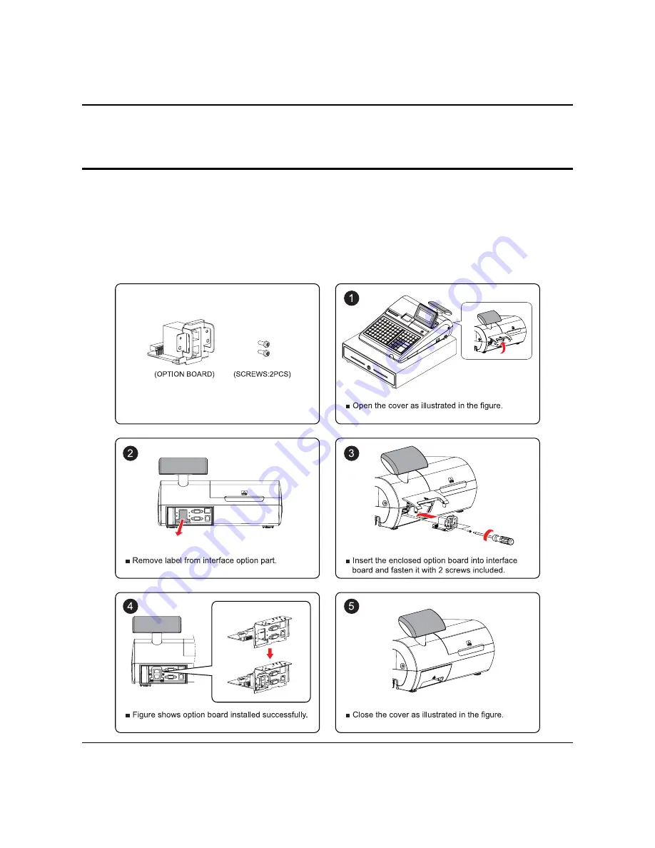
3 Installation and Operation
3-10
SAM4S ER-900/SPS-300 SERIES
3-3 Installation
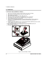
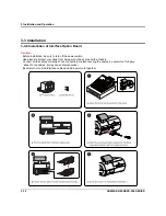
3-3-6 Installation of Interface Option Board
Caution :
· Before installation, be sure to turn off the power switch.
· Use gloves to protect your hand from being cut by the angle and the chassis.
· Connect all the cables correctly. When connecting or disconnecting the cables, be careful not to apply
stress to the cables. (It may cause disconnection)
· Be careful not to bind interface cables and AC power cord together.
Summary of Contents for ER-900 Series
Page 38: ...5 Maintenance and Adjustment 5 2 SAM4S ER 900 SPS 300 SERIES MEMO ...
Page 78: ...7 Exploded View and Parts List 7 34 SAM4S ER 900 SPS 300 SERIES MEMO ...
Page 79: ...SAM4S ER 900 SPS 300 SERIES 8 1 8 PCB Layout and Parts List 8 1 Main PCB ...
Page 84: ...8 PCB Layout and Parts List 8 6 SAM4S ER 900 SPS 300 SERIES 8 2 I F PCB ...
Page 90: ...8 PCB Layout and Parts List 8 12 SAM4S ER 900 SPS 300 SERIES 8 7 OPTION I F 232 USB PCB ...
Page 94: ...8 PCB Layout and Parts List 8 16 SAM4S ER 900 SPS 300 SERIES MEMO ...
Page 95: ...SAM4S ER 900 SPS 300 SERIES 9 1 9 Wiring Diagram 9 1 Main PBA Block Diagram ...
Page 108: ...10 Block Diagram 10 2 SAM4S ER 900 SPS 300 SERIES MEMO ...
Page 130: ...11 22 SAM4S ER 900 SPS 300 SERIES MEMO ...
Page 132: ...ⓒ Shin Heung Precision MAY 2011 Printed in KOREA V1 0 Code No JK68 XXXXXA ...

