4 Disassembly and Assembly
SAM4S ER-900/SPS-300 SERIES
4-3
4-2 Disassembling the Case Lower Block
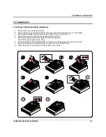
4-2-1 Ass’y Supply (1-Station, Without A/C)
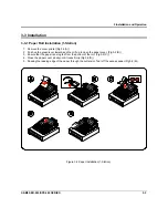
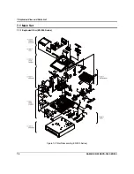
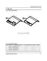
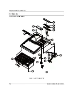
1. Open the ASS'Y COVER PRINTER(A) and lift it off. (Page7-1)
2. Separate the ASS'Y CASE UPPER(C) from the ASS'Y CASE LOWER(F). (Page7-1)
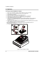
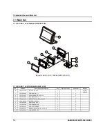
3. Remove the three screws(E22,E32) and then separate the ASS'Y Supply(E23) from the ASS’Y
CASE LOWER(F). (Page7-14,22)
4. Separate a FPC(j) of printer and a cable(bb from Main Board(F6). (Page7-14)
5. Separate the ASS'Y Supply(E23) from the ASS'Y CASE LOWER(F). (Page7-1)
4-2-2 Ass’y Supply(1-Station, With A/C)
1. Open the ASS'Y COVER PRINTER(A) and lift it off. (Page7-1)
2. Separate the ASS'Y CASE UPPER(C) from the ASS'Y CASE LOWER(F). (Page7-1)
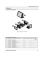
3. Remove the four screws(E22,E32,F20) and then separate the ASS'Y Supply(E23) from the ASS’Y
CASE LOWER(F). (Page7-16,22)
4. Separate a FPC(j) of printer and a cable(bb) from Main Board(F6). (Page7-16)
5. Separate the ASS'Y Supply(E23) from the ASS'Y CASE LOWER(F). (Page7-1)
4-2-3 Ass’y Supply(2-Station, Without A/C)
1. Open the ASS'Y COVER PRINTER(A) and lift it off. (Page7-1)
2. Separate the ASS'Y CASE UPPER(C) from the ASS'Y CASE LOWER(F). (Page7-1)
3. Remove the three screws(E22,E32) and then hold up the ASS'Y Supply(E36) from the ASS’Y
CASE LOWER(F). (Page7-18,22)
4. Separate the two FPCs(j,k) of printer and a cable(bb) from Main Board(F6). (Page7-18)
5. Separate the ASS'Y Supply(E36) from the ASS'Y CASE LOWER(F). (Page7-1)
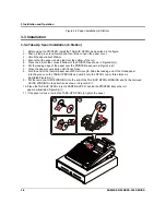
4-2-4 Ass’y Supply(2-Station, With A/C)
1. Open the ASS'Y COVER PRINTER(A) and lift it off. (Page7-1)
2. Separate the ASS'Y CASE UPPER(C) from the ASS'Y CASE LOWER(F). (Page7-1)
3. Remove the four screws(E22,E32,F20) and then hold up the ASS'Y Supply(E36) from the ASS’Y
CASE LOWER(F). (Page7-20,22)
4. Separate the two FPCs(j,k) of printer and a cable(bb) from Main Board(F6). (Page7-20)
5. Separate the ASS'Y Supply(E36) from the ASS'Y CASE LOWER(F). (Page7-1)
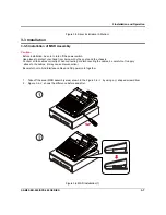
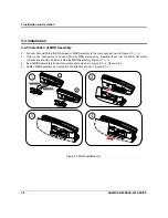
4-2-5 Ass’y Printer(1-Station/ 2-Station, With A/C)
1. Open the ASS'Y COVER PRINTER(A) and lift it off. (Page7-1)
2. Separate the ASS'Y CASE UPPER(C) from the ASS'Y CASE LOWER(F). (Page7-1)
3. Push up the KNOB-RELEASE(E3) and then lift up to open the HOUSING CLAM_2A(E38). (Page7-16)
4. Remove a screw(E47) from the A/C PRINTER(E46) and then remove two FPCs(gg,kk).from the JOINT-
Board(E14). (Page7-16)
5. Separate the ASS'Y PRINTER(E46) from the ASS'Y SUPPLY(E23). (Page7-16)
Summary of Contents for ER-900 Series
Page 38: ...5 Maintenance and Adjustment 5 2 SAM4S ER 900 SPS 300 SERIES MEMO ...
Page 78: ...7 Exploded View and Parts List 7 34 SAM4S ER 900 SPS 300 SERIES MEMO ...
Page 79: ...SAM4S ER 900 SPS 300 SERIES 8 1 8 PCB Layout and Parts List 8 1 Main PCB ...
Page 84: ...8 PCB Layout and Parts List 8 6 SAM4S ER 900 SPS 300 SERIES 8 2 I F PCB ...
Page 90: ...8 PCB Layout and Parts List 8 12 SAM4S ER 900 SPS 300 SERIES 8 7 OPTION I F 232 USB PCB ...
Page 94: ...8 PCB Layout and Parts List 8 16 SAM4S ER 900 SPS 300 SERIES MEMO ...
Page 95: ...SAM4S ER 900 SPS 300 SERIES 9 1 9 Wiring Diagram 9 1 Main PBA Block Diagram ...
Page 108: ...10 Block Diagram 10 2 SAM4S ER 900 SPS 300 SERIES MEMO ...
Page 130: ...11 22 SAM4S ER 900 SPS 300 SERIES MEMO ...
Page 132: ...ⓒ Shin Heung Precision MAY 2011 Printed in KOREA V1 0 Code No JK68 XXXXXA ...

