background image

◀  A - 24  ▶

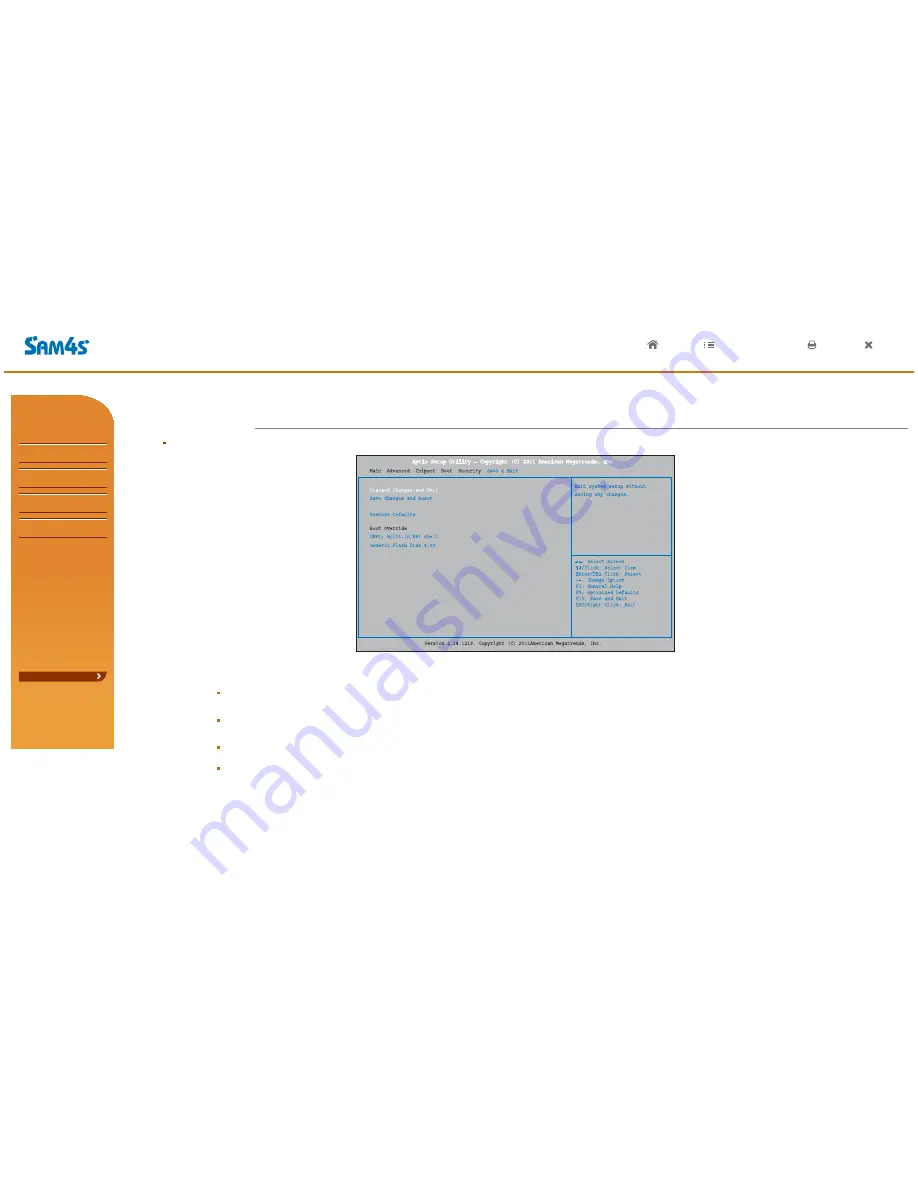
This menu allows you to load the optimal default settings, and save or discard the changes to the BIOS items.

Discard Changes and Exit

Save Changes and Reset

Restore Defaults

Boot Override

Abandon all changes made during the current session and exit setup.

Reset the system after saving the changes.
This selection allows you to reload the BIOS when problem occurs during system booting sequence.

These configurations are factory settings optimized for this system.

This item allows you to exit the system setup without saving any changes.

07. Save & Exit Menu

 Appendix A. BIOS Set up

HOME          LIST          HELP           PRINT          END

?

e-Manual

SPT-3700

System Introduction

System Installation

System Utilization

System Expansion

Appendix A
BIOS set up

Understanding BIOS Set Up

Main Menu

Advanced Menu

Chipset Menu(Host Bridge)

Chipset Menu(South Bridge)

Boot Menu

Security Menu

Save & Exit Menu

Appendix B
System configuration

Summary of Contents for SPT-3700 series

Page 1: ...HOME LIST HELP PRINT END SPT 3700series POS System Electronic Manuals Rev 1 00 1211 E This manual consists of system introduction system expansion and appendix A B...

Page 2: ...System Utilization System expansion appendix A BIOS set up appendix B System configuration This manual provides technical information about the circuits components and construction of the SAM4S POS Sy...

Page 3: ...USB Connection DC Power Connection e Manual SPT 3700 System Utilization Use of Touch Screen POS Driver and Utility Introduction Use of Dual Monitors e Manual SPT 3700 System Expansion System Disassemb...

Page 4: ...A equipment Broadcast telecommunication equipment for business This product is registered for conformity of electromagnetic wave Please be advised that this product be used out of home e Manual SPT 37...

Page 5: ...age if not used properly This symbol highlights important information Warning messages are expressed by several symbols in this manuals Warning messages are imperative sentences as below HOME LIST HEL...

Page 6: ...o not use benzene thinner and alcohol or the procust may be damaged Keep the product away from heaters The product may be damaged overheated or burned Turn on the system after turning on peripheral de...

Page 7: ...ouse Mouse pad option HOME LIST HELP PRINT END e Manual SPT 3700 System Introduction Intro Safety Notices Before Installation or Use Contents System features Specification Options Name and Function of...

Page 8: ...ions It is convenient to change Hard disk and memory It offers basic supports like OS restore anti virus vaccine 15 TFT LCD Touch Screen MSR Magnetic Stripe Reader Option Wall Mount Bracket Option All...

Page 9: ...SReady 2009 POSReady 7 COM Serial port D SUB 9P x 3ports RJ 45 x 2ports COM6 is not allowable when using Option CDP 5V or 12V or RI outputs through COM 1 2 3 4 BIOS setup PARALLEL port D SUB 25P x 1po...

Page 10: ...SPT 3700 on the wall Magnet Type VFD 5 x 7 Dot 20 x 2 Character type 256 x 32 Graphic type LCD 7 17 78cm 800 x 480 16 9 type 15 38 1cm 1024 x 768 4 3 type Optional Specifications HOME LIST HELP PRINT...

Page 11: ...ating lamp for HDD The light is on when data in HDD is being used or read Indicating lamp for power supply The light is on when the system is on Touch LCD Stand Dallas Key Option Using for Dallas secu...

Page 12: ...rd can be used POWER BUTTON Dummy for cable arrangement STAND Turns On Off your system ANGLE ADJUSTMENT LEVER HOME LIST HELP PRINT END e Manual SPT 3700 System Introduction Intro Safety Notices Before...

Page 13: ...ERNET port 8 D SUB 9pin COM Serial port 9 D SUB 25pin printer LPT port 10 D SUB 15pin VGA port 11 2 5 12V DC Output for Rear display 12 DIN 4pin 12V DC Input Input power connection 1 2 3 5 6 8 9 6 1 1...

Page 14: ...on CDP all in one customer display option It shows advertisements or calculation HOME LIST HELP PRINT END e Manual SPT 3700 System Introduction Intro Safety Notices Before Installation or Use Contents...

Page 15: ...2 System Installation HOME LIST HELP PRINT END e Manual SPT 3700 System Introduction System Installation Remove The Cable Cover Remove Cable Tidy Dummy Keyboard Mouse Connection Printer Connection Ser...

Page 16: ...PART 2 System Installation HOME LIST HELP PRINT END e Manual SPT 3700 System Introduction System Installation Remove The Cable Cover Remove Cable Tidy Dummy Keyboard Mouse Connection Printer Connectio...

Page 17: ...Mouse 04 Connecting Printer PART 2 System Installation HOME LIST HELP PRINT END e Manual SPT 3700 System Introduction System Installation Remove The Cable Cover Remove Cable Tidy Dummy Keyboard Mouse...

Page 18: ...k the used voltage of the cash drawer before connection Cash drawer may not work or could be damaged if you connect it with different setup Note Barcode Scanner Cash Drawer 05 Connecting Serial Port D...

Page 19: ...LAN Herb Mouse Key Board CCD Camera USB Memory PART 2 System Installation 07 Connecting RJ 45 LAN Cable 08 Connecting USB device HOME LIST HELP PRINT END e Manual SPT 3700 System Introduction System...

Page 20: ...used by using other products except SAM4S Cautions PART 2 System Installation HOME LIST HELP PRINT END e Manual SPT 3700 System Introduction System Installation Remove The Cable Cover Remove Cable Tid...

Page 21: ...appears again Ball point pens or sharp tools may damage the surface of the touch screen Recalibrate if it is not accurate on touch points Caution 1 2 PART 3 System Utilization 01 Use of Touch Screen...

Page 22: ...a dual monitor Recalibration is also not needed when changing to Single Screen Mode LVDS only whil using Extended Screen Mode Note 3 HOME LIST HELP PRINT END e Manual SPT 3700 System Introduction Syst...

Page 23: ...ity Intorduction Drivers Mother Board Manual System Manual Utility HOME LIST HELP PRINT END e Manual SPT 3700 System Introduction System Installation System Utilization Use of Touch Screen POS Driver...

Page 24: ...Display Utility Adobe Reader MiniPrinter MS Excel Viewer POS Utility HOME LIST HELP PRINT END e Manual SPT 3700 System Introduction System Installation System Utilization Use of Touch Screen POS Driv...

Page 25: ...tered set up according to the system configuration OPOS or OLE Retail POS consists of an architecture for win32 based POS device access The current OPOS driver has been developed in accordance with OP...

Page 26: ...external monitor Press a power button of the system and the external monitor 1 2 The system supports dual monitors that is using two monitors for one system Sub monitor can be displayed a screen copie...

Page 27: ...connector This contents is written based on Windows 7 OS HOME LIST HELP PRINT END 03 Use of Dual Monitors PART 3 System Utilization e Manual SPT 3700 System Introduction System Installation System Ut...

Page 28: ...d screen 4 Additional monitor can be connected to the VGA connector This contents is written based on Windows 7 OS HOME LIST HELP PRINT END 03 Use of Dual Monitors PART 3 System Utilization e Manual S...

Page 29: ...connected to the VGA connector This contents is written based on Windows 7 OS HOME LIST HELP PRINT END 03 Use of Dual Monitors PART 3 System Utilization e Manual SPT 3700 System Introduction System In...

Page 30: ...his contents is written based on Windows 7 OS HOME LIST HELP PRINT END 03 Use of Dual Monitors PART 3 System Utilization e Manual SPT 3700 System Introduction System Installation System Utilization Us...

Page 31: ...This contents is written based on Windows 7 OS HOME LIST HELP PRINT END 03 Use of Dual Monitors PART 3 System Utilization e Manual SPT 3700 System Introduction System Installation System Utilization U...

Page 32: ...GA connector This contents is written based on Windows 7 OS HOME LIST HELP PRINT END 03 Use of Dual Monitors PART 3 System Utilization e Manual SPT 3700 System Introduction System Installation System...

Page 33: ...and select Graphic Properties menu Make sure that Operating Mode of Multiple Displays is set as Extended Desktop Method 1 Method 2 Additional monitor can be connected to the VGA connector This conten...

Page 34: ...Expansion 01 System Disassembly e Manual SPT 3700 System Introduction System Installation System Utilization System Expansion System Disassembly System Reassemble Upgrading Memory Module HDD Replaceme...

Page 35: ...mbly CDP HOME LIST HELP PRINT END e Manual SPT 3700 System Introduction System Installation System Utilization System Expansion System Disassembly System Reassemble Upgrading Memory Module HDD Replace...

Page 36: ...m Introduction System Installation System Utilization System Expansion System Disassembly System Reassemble Upgrading Memory Module HDD Replacement MSR Removal Internal Speaker Removal Touch MSR Board...

Page 37: ...out 7 display Please Jump to 4 8 page Cautions Locking Lever e Manual SPT 3700 System Introduction System Installation System Utilization System Expansion System Disassembly System Reassemble Upgradin...

Page 38: ...em Introduction System Installation System Utilization System Expansion System Disassembly System Reassemble Upgrading Memory Module HDD Replacement MSR Removal Internal Speaker Removal Touch MSR Boar...

Page 39: ...anual SPT 3700 System Introduction System Installation System Utilization System Expansion System Disassembly System Reassemble Upgrading Memory Module HDD Replacement MSR Removal Internal Speaker Rem...

Page 40: ...Manual SPT 3700 System Introduction System Installation System Utilization System Expansion System Disassembly System Reassemble Upgrading Memory Module HDD Replacement MSR Removal Internal Speaker Re...

Page 41: ...he cover HOME LIST HELP PRINT END e Manual SPT 3700 System Introduction System Installation System Utilization System Expansion System Disassembly System Reassemble Upgrading Memory Module HDD Replace...

Page 42: ...be up to 4GB Once the memory is installed BIOS automatically recognizes the memory type capacity and speed PART 4 System Expansion 03 Upgrading Memory Module HOME LIST HELP PRINT END e Manual SPT 370...

Page 43: ...ART 4 System Expansion 04 HDD Replacement HOME LIST HELP PRINT END e Manual SPT 3700 System Introduction System Installation System Utilization System Expansion System Disassembly System Reassemble Up...

Page 44: ...before replacing The 2 5 inch SATA interface is the only interface supported PART 4 System Expansion 04 HDD Replacement HOME LIST HELP PRINT END e Manual SPT 3700 System Introduction System Installati...

Page 45: ...ME LIST HELP PRINT END e Manual SPT 3700 System Introduction System Installation System Utilization System Expansion System Disassembly System Reassemble Upgrading Memory Module HDD Replacement MSR Re...

Page 46: ...e Manual SPT 3700 System Introduction System Installation System Utilization System Expansion System Disassembly System Reassemble Upgrading Memory Module HDD Replacement MSR Removal Internal Speaker...

Page 47: ...ion 07 Touch MSR Board Removal HOME LIST HELP PRINT END e Manual SPT 3700 System Introduction System Installation System Utilization System Expansion System Disassembly System Reassemble Upgrading Mem...

Page 48: ...PRINT END e Manual SPT 3700 System Introduction System Installation System Utilization System Expansion System Disassembly System Reassemble Upgrading Memory Module HDD Replacement MSR Removal Interna...

Page 49: ...END e Manual SPT 3700 System Introduction System Installation System Utilization System Expansion System Disassembly System Reassemble Upgrading Memory Module HDD Replacement MSR Removal Internal Spea...

Page 50: ...END e Manual SPT 3700 System Introduction System Installation System Utilization System Expansion System Disassembly System Reassemble Upgrading Memory Module HDD Replacement MSR Removal Internal Spe...

Page 51: ...Cable USB Board I O Extension Board PART 4 System Expansion 11 I O Extension Board Removal HOME LIST HELP PRINT END e Manual SPT 3700 System Introduction System Installation System Utilization System...

Page 52: ...m Expansion 12 Main Board Removal HOME LIST HELP PRINT END e Manual SPT 3700 System Introduction System Installation System Utilization System Expansion System Disassembly System Reassemble Upgrading...

Page 53: ...Caution DALLAS Cable LCD Bracket Front Display LED Cable MSR Cable Touch Cable Main Interface Cable PART 4 System Expansion 13 Touch Panel Removal HOME LIST HELP PRINT END e Manual SPT 3700 System Int...

Page 54: ...materials Take care to avoid damage Caution Hand Touch panel Hand PART 4 System Expansion 13 Touch Panel Removal HOME LIST HELP PRINT END e Manual SPT 3700 System Introduction System Installation Syst...

Page 55: ...enter for touch panel removal and replacement Caution DALLAS Cable LCD Bracket Front Display LED Cable MSR Cable Touch Cable Main Interface Cable HOME LIST HELP PRINT END e Manual SPT 3700 System Intr...

Page 56: ...cratches Touch panel and cables are made of sensitive materials Take care to avoid damage Caution Hand Touch panel Hand HOME LIST HELP PRINT END e Manual SPT 3700 System Introduction System Installati...

Page 57: ...e Manual SPT 3700 System Introduction System Installation System Utilization System Expansion System Disassembly System Reassemble Upgrading Memory Module HDD Replacement MSR Removal Internal Speaker...

Page 58: ...o enter SETUP message When this message show up press DEL or Delete key to enter SETUP screen When checking HDD type and capacity after HDD replacement When changing booting sequence When reflecting u...

Page 59: ...S Set up BIOS provides configuration and set up information for driving the main board BIOS values are saved in CMOS ROM on the main board 01 Understanding BIOS Set Up HOME LIST HELP PRINT END e Manua...

Page 60: ...configuration values which the mainboard manufacturer set up F10 Save and Exit Save changed values and exit setup program BIOS provides configuration and set up information for driving the main board...

Page 61: ...eded set up the date on System Date The date format is Month Day Year in order Move to the item with Tab or Enter key and change it with Space or key Appendix A BIOS Set up HOME LIST HELP PRINT END e...

Page 62: ...Option ROM 03 Advanced Menu Appendix A BIOS Set up HOME LIST HELP PRINT END e Manual SPT 3700 System Introduction System Installation System Utilization System Expansion Appendix A BIOS set up Underst...

Page 63: ...Register This item enables or disables VGA Palette Registers Snooping This item enables or disables PCI Device to generate PERR This item enables or disables PCI Device to generate SERR 03 Advanced M...

Page 64: ...Lock of Legacy The item enables or disables S3 Video repost The item enables the system to wake from S5 using PME event This item enables or disables the system to wake on by alarm event When this ite...

Page 65: ...up the operating system executes the CPUID instruction to identify the processor and its capabilities Before it can do so it must first query the processor to find out the highest input value CPUID r...

Page 66: ...tup for SPT 3700 is AHCI mode If you change this setup carelessly the system may not be booted Caution 03 Advanced Menu Appendix A BIOS Set up HOME LIST HELP PRINT END e Manual SPT 3700 System Introdu...

Page 67: ...Enable RTC wake timer as S3 entry iFFS invocation upon critical battery wake 03 Advanced Menu Appendix A BIOS Set up HOME LIST HELP PRINT END e Manual SPT 3700 System Introduction System Installation...

Page 68: ...thout EHCI hand off support The EHCI ownership change should be claimed by EHCI driver The time out value is for Control Bulk and Interrupt transfers This is the USB mass storage device Start Unit com...

Page 69: ...ing the system in power off status after power recovers Power On Powering on the system immediately when power returns Last State Recover the system as before a power fail or interrupts occurs This it...

Page 70: ...current voltage of CPU Shows current voltage of DRAM 03 Advanced menu Appendix A BIOS Set up HOME LIST HELP PRINT END e Manual SPT 3700 System Introduction System Installation System Utilization Syste...

Page 71: ...ows you to select PCI IRQ Sharing for QS Ex Windows and ISA IRQ for DOS 03 Advanced menu Appendix A BIOS Set up HOME LIST HELP PRINT END e Manual SPT 3700 System Introduction System Installation Syste...

Page 72: ...ltage This item allows you to set the output voltage value of Serial port 1 2 3 4 PIN9 type 03 Advanced menu Appendix A BIOS Set up HOME LIST HELP PRINT END e Manual SPT 3700 System Introduction Syste...

Page 73: ...sible for main memory RAM and graphic control 04 Chipset Menu Host Bridge Appendix A BIOS Set up HOME LIST HELP PRINT END e Manual SPT 3700 System Introduction System Installation System Utilization S...

Page 74: ...oller Chipset is the device supporting the data transfer control between CPU and peripheral components 04 Chipset Menu Host Bridge Appendix A BIOS Set up HOME LIST HELP PRINT END e Manual SPT 3700 Sys...

Page 75: ...tion used by the Internal Graphics Device This item selects the Active LVDS Configuration This item configures the Fixed Graphics Memory Size Chipset is the device supporting the data transfer control...

Page 76: ...of Active State Power Management on both NB and SB sides of the DMI Link This item selects a PCI Express High Priority Port This item enables or disables the High Precision Event Timer This item sele...

Page 77: ...SB devices 04 05 Chipset Menu South Bridge Appendix A BIOS Set up 04 Chipset Menus This section describes configuring the PCI bus system PCI or Personal Computer Interconnect is a system which allows...

Page 78: ...gic You can use this item to set SIRQ mode 04 05 Chipset Menu South Bridge Appendix A BIOS Set up South bridge This section describes configuring the PCI bus system PCI IDE USB devices are set in this...

Page 79: ...Enabled it allows the Option ROMs to trap Interrupt 19 When this item is set to Enabled BIOS will let user know boot success with beep This item enables or disables boot from the UEFI Devices Items i...

Page 80: ...er Password 06 Security Menu Appendix A BIOS Set up HOME LIST HELP PRINT END e Manual SPT 3700 System Introduction System Installation System Utilization System Expansion Appendix A BIOS set up Unders...

Page 81: ...when problem occurs during system booting sequence These configurations are factory settings optimized for this system This item allows you to exit the system setup without saving any changes 07 Save...

Page 82: ...Block Diagram EIC10 SAM D2550 e Manual SPT 3700 System Introduction System Installation System Utilization System Expansion Appendix A BIOS Set up Appendix B System configuration System Block Diagram...

Page 83: ...Intel Atom CPU D2700 2 13GHz or D2550 1 86GHz Intel NM10 South Bridge PCI SLOT USB 5 LPT SPEAKER LINE IN JACK LINE OUT JACK MIC IN JACK LAN USB A TYPE SERIAL COM1 SERIAL COM2 Appendix B System Configu...

Page 84: ...Short 5 6 Short Voltage RI 5V 12V Default BIOS Clear Jumper JCMOS1 Serial JPC5 6 Voltage Jumper Serial5 JPC5 Serial6 JPC6 Inverter Voltage Jumper JLV2 3 1 3 1 5 1 6 2 02 Main Board Configuration Appen...

Page 85: ...TS Clear to send CTS Ring 5V or 12V COM3 COM6 RJ45 Pin 1 2 3 4 5 6 7 8 Assignment RI 15V 12V DSR TXD RXD RTS LTS GND DTR 6 9 1 5 1 8 1 8 02 Main Board Configuration Appendix B System Configuration e M...

Page 86: ...I 0 MDI 1 MDI 1 MDI 2 MDI 2 MDI 3 MDI 3 4 1 1 4 1 8 02 Main Board Configuration Appendix B System Configuration e Manual SPT 3700 System Introduction System Installation System Utilization System Expa...
Page 87: ...PERIPHREQST FAULT REVERSEQST SLCTIN GND EPP WRITE PD0 PD1 PD2 PD3 PD4 PD5 PD6 PD7 NTR WAIT PE SELECT DATASTB FAULT RESET ADDRSTB GND In Out I O I O I O I O I O I O I O I O I O I I I I O I O O 02 Main...

Page 88: ...lection Switch for Cash Drawer 1 6 Switch Selection OFF ON Voltage 12V Default 24V 02 Main Board Configuration Appendix B System Configuration e Manual SPT 3700 System Introduction System Installation...

Page 89: ...3 4 Description 12V 12V GND GND 02 Main Board Configuration Appendix B System Configuration e Manual SPT 3700 System Introduction System Installation System Utilization System Expansion Appendix A BI...

Page 90: ...4 1 JK72 20304A PMO STAND 1 Y A4 2 JK70 20101B IPR HINGE SUPPORT R 1 Y A4 3 JK70 20101A IPR HINGE SUPPORT L 1 Y A4 4 JK73 11023A RMO FOOT RUBBER 4 Y A4 5 S600300011A SCREW TAPTITE 2 Y A4 6 JK72 20303A...

Page 91: ...SCREW TAPTITE 11 Y B17 S600100016A SCREW MACHINE 3 Y B18 JK95 70480A MEA BRKT SD CARD 1 Y B19 S600100016A SCREW MACHINE 3 Y B20 JK92 10018E PBA SUB USB B D SPT 3700 SVC 1 Y B21 S600100016A SCREW MACH...

Page 92: ...C6 JK73 11017A RMO RUBBER INSULATOR 4 Y C7 S600100036A SCREW MACHINE HAND 4 Y C8 JK95 70209C UNIT HDD 1 Y C9 JK70 20090B IPR BRKT HDD 1 Y C10 JK73 11017A RMO RUBBER INSULATOR 2 Y C11 S600100036A SCREW...

Page 93: ...A CABLE 1 Y NO PART CODE PARTS NAME Q TY Serviceable REMARK E OPTION 1 Y E1 1 Y E2 1 Y E3 2 Y E4 1 Y E5 1 Y E6 1 Y E7 1 Y E8 1 Y E9 1 Y E10 1 Y E11 1 Y QCD V202 OPTION CDP CHARACTER QCD G256 OPTION CD...

Reviews: