background image

 02. Mainboard Overview

System Structure

◀  B - 3  ▶

Main Jumper Setting

SPT-7000

Introduction

System Installation

System Use

System Expansion 
& Dismantle

Appendix A

System Set-Up

Appendix B

System Structure


System Block


Mainboard Overview

   Exploded View
  

HOME          Contents          Help          Print          Exit

?

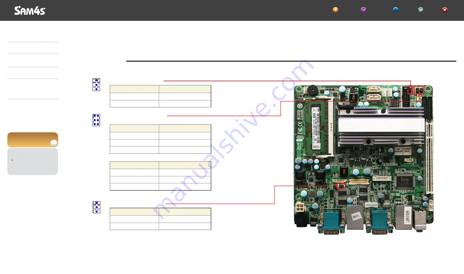
Jumper Setting

1 - 2 Short
2 - 3 Short

Voltage

Normal Operation(Default)

CMOS Clear

Jumper Setting

1 - 2 Short
2 - 3 Short

Voltage

5V

12V (Default)

Jumper Setting

1 - 2 Short
3 - 4 Short
5 - 6 Short

Voltage

RI

5V (Default)

12V

Jumper Setting

1 - 2 Short
3 - 4 Short
5 - 6 Short

Voltage

RI

5V

12V (Default)

BIOS Clear Jumper(JCOMS1)

Serial(JPC5/6) Voltage Jumper
- Serial5(JPC5)

- Serial6(JPC6)

Inverter Voltage Jumper(JLV2)

3

1

3

1

5

1

6

2

Summary of Contents for SPT-7000 Series

Page 1: ...Leading the way with Reliability Features and Value SPT 7000series e Manual Help Print Exit Rev 1 00 1204 K...

Page 2: ...ement without prior notice Notice to Users This device classified for the commerce is compatible with A Class Electromagnetic Wave Registration So it is recommended to be used in shops or stores outsi...

Page 3: ...Set Plug Cable Management System On Off System On System Off System Use Keyboard Use Touch screen Use About POS Driver and Utility Dual Monitor Use System Expansion Dismantle System Dismantling Assem...

Page 4: ...such as electrical circuit components and structure regarding Sam4s POS Point of Sale System SPT 7000 The outer design or specifications are subject to change for quality improvement without prior no...

Page 5: ...ay differ from that contained in other Sam4s publications This device complies with part 15 of the FCC Rules Class A digital device References Introduction Notification Notification References Alert m...

Page 6: ...rm the procedure correctly This indicates information that could help the user use the product more efficiently This manual uses the following conventions to show the alert messages An alert message c...

Page 7: ...yboard Option Quick Manual Power Cable 1 4 Introduction Notification Unpacking System Features Part Name and Function System Installation System Use System Expansion Dismantle Appendix A System Set Up...

Page 8: ...rable type Also you can organize the cables easily in any surrounding This POS system can make all in one touch screen internal printer MSR SCR and customer display And installation is easy and conven...

Page 9: ...x 1 USB 2 0 Connector Left Side x 2 Rear Side x 4 LAN Connector RJ45 port x 1 8 pin Cash Drawer RJ11 port x 1 6 pin VGA Connector VGA port x 1 15 pin DC Output Jack 12V output port x 1 Audio Line Out...

Page 10: ...rdness 3H Hitting Life 35 million times 60W Adaptor AC INPUT AC 100 240V 50 60Hz 1 5A DC OUTPUT 12V 5 0A Display Touch Panel Power Supply System Specifications General Specifications Introduction Noti...

Page 11: ...240V 50Hz 60Hz 1 5A DC OUTPUT 24V 2 5A Receipt Printer Touch Panel Customer Display MSR Magnetic Stripe Reader DALLAS KEY Finger Printer Reader Cfast SOCKET RAISER CARD Scanner Smart Card Reader TFT L...

Page 12: ...rt Name and Function Front View Introduction Payment Module Light Payment Module Scanner Module for Barcode Recognition Printer Light Frame Stand Dallas or Fingerprint Module for Security Power Light...

Page 13: ...Printer Cover Receipt Printer Feed Button for Paper 1 10 Introduction Notification Unpacking System Features Part Name and Function Front View Half Side View Side View Rear View System Installation S...

Page 14: ...cting USB Interface such as USB Keyboard Mouse etc Can use Cfast Memory 1 11 Introduction Notification Unpacking System Features Part Name and Function Front View Half Side View Side View Rear View Sy...

Page 15: ...and AC Power Plug In case of connecting peripherals dismantle the cover Remove this cover and you can install customer display CDP Dual LCD Dual LCD 1 12 Introduction Notification Unpacking System Fea...

Page 16: ...For connecting external speaker DVR Card Port Option For connecting DVR card integrating camera Max 4 channels Parallel Port For connecting parallel interface such as printer RJ11 Cash Drawer Port For...

Page 17: ...Keep this system away from humidity dust direct sunlight and high temperature Always keep it in a cool area Make sure the power voltage is within safety range and being adjusted properly to the value...

Page 18: ...jury from the edge of the equipment Caution Connecting Peripherals Remove Interface Cover First remove Interface Cover at the rear of the system HOME Contents Help Print Exit Introduction System Insta...

Page 19: ...es We recommend you to use Sam4s Cash Drawer because of different cable specifications by each manufacturer Note Barcode Scanner Cash Drawer HOME Contents Help Print Exit Introduction System Installat...

Page 20: ...Connecting USB Device Mouse Keyboard CCD Camera LAN Hub Introduction System Installation Make sure of installation area Before connecting peripherals Connecting Peripherals Connecting Serial Port Devi...

Page 21: ...ecting peripherals Connecting Peripherals Connecting Serial Port Devices such as Barcode Scanner Connecting RJ 11 Cash Drawer Connecting RJ 45 LAN Cable Connecting USB Device Connecting PS Module Conn...

Page 22: ...Jam Wrong Positioned Beep Sound No Sound No Sound A Long Beep Sound Repeat Pee Pee Two times Short Beep Sound PeePee PeePee Three times Short Beep Sound PeePeePee PeePeePee Status LED Green Color Led...

Page 23: ...embly HOME Contents Help Print Exit Introduction System Installation Make sure of installation area Before connecting peripherals Connecting Peripherals Connecting Serial Port Devices such as Barcode...

Page 24: ...small amount paper as shown and close the cover 5 Tear off the paper as shown Introduction System Installation Make sure of installation area Before connecting peripherals Connecting Peripherals Conne...

Page 25: ...nting following message Self Test Mode Self Test can check products for defects or disorder The procedure for Self Test is as follows Printer Power Status LED Feed Button HOME Contents Help Print Exit...

Page 26: ...d paper continuously Printer Power Status LED Feed Button Introduction System Installation Make sure of installation area Before connecting peripherals Connecting Peripherals Connecting Serial Port De...

Page 27: ...ch the printer thermal head Be careful that the printer head is not damaged Caution Paper Roller Printer Head HOME Contents Help Print Exit Introduction System Installation Make sure of installation a...

Page 28: ...LED blinks when it enters the ERROR status about 60ms 60ms about 1 3sec 1300ms ON OFF No paper Buzzer Sound HOME Contents Help Print Exit Introduction System Installation Make sure of installation ar...

Page 29: ...about 500ms ON OFF Cutter Jam LED Buzzer Status HOME Contents Help Print Exit Introduction System Installation Make sure of installation area Before connecting peripherals Connecting Peripherals Conne...

Page 30: ...ms about 500ms ON OFF Cutter Not Home LED and Buzzer Status HOME Contents Help Print Exit Introduction System Installation Make sure of installation area Before connecting peripherals Connecting Perip...

Page 31: ...ver HOME Contents Help Print Exit Introduction System Installation Make sure of installation area Before connecting peripherals Connecting Peripherals Connecting Serial Port Devices such as Barcode Sc...

Page 32: ...n System Installation Make sure of installation area Before connecting peripherals Connecting Peripherals Connecting Serial Port Devices such as Barcode Scanner Connecting RJ 11 Cash Drawer Connecting...

Page 33: ...erals Connecting Peripherals Connecting Serial Port Devices such as Barcode Scanner Connecting RJ 11 Cash Drawer Connecting RJ 45 LAN Cable Connecting USB Device Connecting PS Module Connecting Securi...

Page 34: ...DVR Card Connecting AC Power Cord to the Set Plug Cable Management System On Off System Use System Expansion Dismantle Appendix A System Set Up Appendix B System Structure SPT 7000 03 Connecting Peri...

Page 35: ...ipherals Connecting Serial Port Devices such as Barcode Scanner Connecting RJ 11 Cash Drawer Connecting RJ 45 LAN Cable Connecting USB Device Connecting PS Module Connecting Security Scanner Module Co...

Page 36: ...awer Connecting RJ 45 LAN Cable Connecting USB Device Connecting PS Module Connecting Security Scanner Module Connecting Receipt Printer Receipt Printer Dismantle the Cover for Customer Displays Conne...

Page 37: ...stem 4 Windows initial screen will appear after a while After installation of the system proceed to power on the system with following steps HOME Contents Help Print Exit Power Light Power Button Intr...

Page 38: ...omputer on popup menu 3 System will be shut down when Turn Off is clicked Introduction System Installation Make sure of installation area Before connecting peripherals Connecting Peripherals System On...

Page 39: ...and arrow keys It is a toggle key like C Lock and Scroll Lock Its state is commonly represented by an LED light built into the keyboard Do special functions in applications Make the current screenshot...

Page 40: ...f the red circle appears again Ball point pen or sharpness tools may damage to surface of touch screen To recalibrate the touch screen please follow the procedure blow Caution 1 2 Recalibrate if it is...

Page 41: ...r On contrary recalibration is also no need in case of being changed into Single Screen Mode LVDS only while using Extended Screen Mode Note 3 Recalibrate if it is not accurate on touch points Introdu...

Page 42: ...r folder of C driver Introduction System Installation System Use Keyboard Use Touch screen Use About POS Driver and Utility Dual Monitor Use System Expansion Dismantle Appendix A System Set Up Appendi...

Page 43: ...er file Self Test Program Test utility for peripherals of POS VFD Customer Display Utility Adobe Reader MiniPrinter MS Excel Viewer POS Utility Introduction System Installation System Use Keyboard Use...

Page 44: ...xx exe file in OPOS folder All components will be automatically registered set up according to the system configuration OPOS or OLE Retail POS consists of an architecture for win32 based POS device a...

Page 45: ...bottom of system VGA connector is shown Connect to external monitor when the system is turned off Connect a power cable to external monitor Press a power button of the system and the external monitor...

Page 46: ...Additional monitor can be connected to the VGA connector This contents is written based on Windows 7 OS Introduction System Installation System Use Keyboard Use Touch screen Use About POS Driver and U...

Page 47: ...n this case the dual monitor shows a duplicated screen 4 Additional monitor can be connected to the VGA connector This contents is written based on Windows 7 OS Introduction System Installation System...

Page 48: ...04 Dual Monitor Use Additional monitor can be connected to the VGA connector This contents is written based on Windows 7 OS Introduction System Installation System Use Keyboard Use Touch screen Use A...

Page 49: ...onitor can be connected to the VGA connector This contents is written based on Windows 7 OS Introduction System Installation System Use Keyboard Use Touch screen Use About POS Driver and Utility Dual...

Page 50: ...monitor can be connected to the VGA connector This contents is written based on Windows 7 OS Introduction System Installation System Use Keyboard Use Touch screen Use About POS Driver and Utility Dual...

Page 51: ...e Additional monitor can be connected to the VGA connector This contents is written based on Windows 7 OS Introduction System Installation System Use Keyboard Use Touch screen Use About POS Driver and...

Page 52: ...of Windows tray area and select Graphic Properties menu Make sure that Operating Mode of Multiple Displays is set as Extended Desktop Method 1 Method 2 04 Dual Monitor Use Additional monitor can be c...

Page 53: ...rds Removal Main Memory Removal Remove Display Assembly Remove MSR Remove Display Board Remove Touch Panel LCD Appendix A System Set Up Appendix B System Structure SPT 7000 HOME Contents Help Print Ex...

Page 54: ...Use System Expansion Dismantle System Dismantling Assembling HDD Replacement Internal Speaker USB Removal Receipt Printer Board Removal Scanner Dallas Removal SMPS Removal Mainboard ASSY Removal Vario...

Page 55: ...ntling Assembling HDD Replacement Internal Speaker USB Removal Receipt Printer Board Removal Scanner Dallas Removal SMPS Removal Mainboard ASSY Removal Various Boards Removal Main Memory Removal Remov...

Page 56: ...Use System Expansion Dismantle System Dismantling Assembling HDD Replacement Internal Speaker USB Removal Receipt Printer Board Removal Scanner Dallas Removal SMPS Removal Mainboard ASSY Removal Vari...

Page 57: ...g Dismantling DUAL 7 Introduction System Installation System Use System Expansion Dismantle System Dismantling Assembling HDD Replacement Internal Speaker USB Removal Receipt Printer Board Removal Sca...

Page 58: ...ing DUAL 15 Introduction System Installation System Use System Expansion Dismantle System Dismantling Assembling HDD Replacement Internal Speaker USB Removal Receipt Printer Board Removal Scanner Dall...

Page 59: ...Assembling Dismantling DUAL 15 Introduction System Installation System Use System Expansion Dismantle System Dismantling Assembling HDD Replacement Internal Speaker USB Removal Receipt Printer Board...

Page 60: ...roduction System Installation System Use System Expansion Dismantle System Dismantling Assembling HDD Replacement Internal Speaker USB Removal Receipt Printer Board Removal Scanner Dallas Removal SMPS...

Page 61: ...wer assemble them in reverse order Introduction System Installation System Use System Expansion Dismantle System Dismantling Assembling HDD Replacement Internal Speaker USB Removal Receipt Printer Boa...

Page 62: ...unlock it Then take it out upwards remove the cable Introduction System Installation System Use System Expansion Dismantle System Dismantling Assembling HDD Replacement Internal Speaker USB Removal R...

Page 63: ...with System Set up chapter in appendix A Introduction System Installation System Use System Expansion Dismantle System Dismantling Assembling HDD Replacement Internal Speaker USB Removal Receipt Prin...

Page 64: ...ard Introduction System Installation System Use System Expansion Dismantle System Dismantling Assembling HDD Replacement Internal Speaker USB Removal Receipt Printer Board Removal Scanner Dallas Remov...

Page 65: ...m the body Receipt Printer Board Removal Introduction System Installation System Use System Expansion Dismantle System Dismantling Assembling HDD Replacement Internal Speaker USB Removal Receipt Print...

Page 66: ...stem Installation System Use System Expansion Dismantle System Dismantling Assembling HDD Replacement Internal Speaker USB Removal Receipt Printer Board Removal Scanner Dallas Removal SMPS Removal Mai...

Page 67: ...push the left side to assemble 3 Turn on the printer power then check printer is well assembled Receipt Printer Assembling about 15 Upper part Printer cover part Introduction System Installation Syste...

Page 68: ...roduction System Installation System Use System Expansion Dismantle System Dismantling Assembling HDD Replacement Internal Speaker USB Removal Receipt Printer Board Removal Scanner Dallas Removal SMPS...

Page 69: ...stem Installation System Use System Expansion Dismantle System Dismantling Assembling HDD Replacement Internal Speaker USB Removal Receipt Printer Board Removal Scanner Dallas Removal SMPS Removal Mai...

Page 70: ...sembling Introduction System Installation System Use System Expansion Dismantle System Dismantling Assembling HDD Replacement Internal Speaker USB Removal Receipt Printer Board Removal Scanner Dallas...

Page 71: ...CARD HUB BOARD SCANNER DALLAS FPR Introduction System Installation System Use System Expansion Dismantle System Dismantling Assembling HDD Replacement Internal Speaker USB Removal Receipt Printer Boar...

Page 72: ...SD board on the dummy cover Removal Introduction System Installation System Use System Expansion Dismantle System Dismantling Assembling HDD Replacement Internal Speaker USB Removal Receipt Printer Bo...

Page 73: ...System Installation System Use System Expansion Dismantle System Dismantling Assembling HDD Replacement Internal Speaker USB Removal Receipt Printer Board Removal Scanner Dallas Removal SMPS Removal M...

Page 74: ...tallation System Use System Expansion Dismantle System Dismantling Assembling HDD Replacement Internal Speaker USB Removal Receipt Printer Board Removal Scanner Dallas Removal SMPS Removal Mainboard A...

Page 75: ...System Expansion Dismantle System Dismantling Assembling HDD Replacement Internal Speaker USB Removal Receipt Printer Board Removal Scanner Dallas Removal SMPS Removal Mainboard ASSY Removal Various B...

Page 76: ...r check if it is installed properly Introduction System Installation System Use System Expansion Dismantle System Dismantling Assembling HDD Replacement Internal Speaker USB Removal Receipt Printer Bo...

Page 77: ...sembling HDD Replacement Internal Speaker USB Removal Receipt Printer Board Removal Scanner Dallas Removal SMPS Removal Mainboard ASSY Removal Various Boards Removal Main Memory Removal Remove Display...

Page 78: ...bling HDD Replacement Internal Speaker USB Removal Receipt Printer Board Removal Scanner Dallas Removal SMPS Removal Mainboard ASSY Removal Various Boards Removal Main Memory Removal Remove Display As...

Page 79: ...ystem Installation System Use System Expansion Dismantle System Dismantling Assembling HDD Replacement Internal Speaker USB Removal Receipt Printer Board Removal Scanner Dallas Removal SMPS Removal Ma...

Page 80: ...board Introduction System Installation System Use System Expansion Dismantle System Dismantling Assembling HDD Replacement Internal Speaker USB Removal Receipt Printer Board Removal Scanner Dallas Rem...

Page 81: ...of the system 2 Remove I F rear covers 3 Push the top cover to remove Then remove a screw push the dummy cover to the upper side 4 Pull the levers in both sides to remove the memory Introduction Syst...

Page 82: ...back side after lifting display and disassemble Be careful not to cut off harness Assemble in retrograde order and check the display is correctly assembled Introduction System Installation System Use...

Page 83: ...e Introduction System Installation System Use System Expansion Dismantle System Dismantling Assembling HDD Replacement Internal Speaker USB Removal Receipt Printer Board Removal Scanner Dallas Removal...

Page 84: ...System Use System Expansion Dismantle System Dismantling Assembling HDD Replacement Internal Speaker USB Removal Receipt Printer Board Removal Scanner Dallas Removal SMPS Removal Mainboard ASSY Remova...

Page 85: ...very carefully 2 Unscrew 3 screws and disconnect Touch Board TOUCH Cable Introduction System Installation System Use System Expansion Dismantle System Dismantling Assembling HDD Replacement Internal...

Page 86: ...It may happen defectives while disconnecting LCD and Touch Panel due to dust or mishandling Caution Remove Touch Panel LCD Assembly of Touch Panel and LCD Introduction System Installation System Use...

Page 87: ...n the system and the system will show Press DEL to enter SETUP message When this message show up press DEL or Delete key to enter SETUP screen When checking HDD type and capacity after HDD replacement...

Page 88: ...up Preview Set up means that the system configuration information is memorized on BIOS The set up data is saved in a special area of memory called CMOS ROM SPT 7000 Introduction System Installation Sy...

Page 89: ...F9 Load Optimal Defaults Load default configuration values which the mainboard manufacturer set up F10 Save and Exit Save changed values and exit setup program 01 System Set up Preview Set up means t...

Page 90: ...date format is Month Day Year in order Move to the item with Tab or Enter key and change it with Space or key Use this menu for basic system setup such as time date and etc and system information SPT...

Page 91: ...ROM Use this menu for basic system setup such as time date and etc and system information SPT 7000 Introduction System Installation System Use System Expansion Dismantle Appendix A System Set Up Syst...

Page 92: ...ter This item enables or disables VGA Palette Registers Snooping This item enables or disables PCI Device to generate PERR This item enables or disables PCI Device to generate SERR SPT 7000 Introducti...

Page 93: ...f Legacy The item enables or disables S3 Video repost The item enables the system to wake from S5 using PME event This item enables or disables the system to wake on by alarm event When this item is e...

Page 94: ...e operating system executes the CPUID instruction to identify the processor and its capabilities Before it can do so it must first query the processor to find out the highest input value CPUID recogni...

Page 95: ...uration for SATA controller SPT 7000 Introduction System Installation System Use System Expansion Dismantle Appendix A System Set Up System Set up Preview Main Menu Advanced Menu Chipset Menu Boot Men...

Page 96: ...RTC wake timer as S3 entry iFFS invocation upon critical battery wake SPT 7000 Introduction System Installation System Use System Expansion Dismantle Appendix A System Set Up System Set up Preview Ma...

Page 97: ...port The EHCI ownership change should be claimed by EHCI driver The time out value is for Control Bulk and Interrupt transfers This is the USB mass storage device Start Unit command time out This is m...

Page 98: ...the system immediately when power returns Last State 1 Leaving the system in power off if the system shuts down at DC off status 2 Powering on the system immediately if the system shuts down at DC on...

Page 99: ...Shows current voltage of DRAM 03 Advanced Menu SPT 7000 Introduction System Installation System Use System Expansion Dismantle Appendix A System Set Up System Set up Preview Main Menu Advanced Menu Ch...

Page 100: ...RQ Sharing for QS Ex Windows and ISA IRQ for DOS 03 Advanced Menu SPT 7000 Introduction System Installation System Use System Expansion Dismantle Appendix A System Set Up System Set up Preview Main Me...

Page 101: ...port pin 9 type is Ring Vcc 5V Vcc 12V This item allows you to select Serial port pin 2 type is Ring Vcc 5V Vcc 12V 03 Advanced Menu SPT 7000 Introduction System Installation System Use System Expans...

Page 102: ...ices to operate at speeds nearing the speed of the CPU itself uses when communicating with its own special components SPT 7000 Introduction System Installation System Use System Expansion Dismantle Ap...

Page 103: ...his section describes configuring the PCI bus system PCI or Personal Computer Interconnect is a system which allows I O devices to operate at speeds nearing the speed of the CPU itself uses when commu...

Page 104: ...al Graphics Device This item selects the Active LVDS Configuration This item configures the Fixed Graphics Memory Size 04 Chipset Menus This section describes configuring the PCI bus system PCI or Per...

Page 105: ...y Port This item enables or disables the High Precision Event Timer This item selects a minimum assertion width of the SLP_S4 signal 04 Chipset Menus This section describes configuring the PCI bus sys...

Page 106: ...to control USB ports 04 Chipset Menus This section describes configuring the PCI bus system PCI or Personal Computer Interconnect is a system which allows I O devices to operate at speeds nearing the...

Page 107: ...e this item to set SIRQ mode 04 Chipset Menus This section describes configuring the PCI bus system PCI or Personal Computer Interconnect is a system which allows I O devices to operate at speeds near...

Page 108: ...unction When this item is set to Enabled it allows the Option ROMs to trap Interrupt 19 When this item is set to Enabled BIOS will let user know boot success with beep This item enables or disables bo...

Page 109: ...word This menu allows you to provide revise supervisor and user password SPT 7000 Introduction System Installation System Use System Expansion Dismantle Appendix A System Set Up System Set up Preview...

Page 110: ...ence These configurations are factory settings optimized for this system This item allows you to exit the system setup without saving any changes This menu allows you to load the optimal default setti...

Page 111: ...NM10 Tigerpoint 2 1W CEDARVIEW D2500 1 86 GHz 10W D2550 1 86 GHz 10W D2700 2 13 GHz 10W colay with N2600 N2800 mobile Processor VRM 12 IMVP 7 ISL95837 VCORE 0 91V 1 21V LVDS DIO DIMMA1 DIMMA2 HD Audi...

Page 112: ...ock Mainboard Overview Exploded View HOME Contents Help Print Exit HDD POWER F PANEL USB7 GPIO IN OUT USB5 6 SERIAL COM5 6 Intel Atom CPU D2550 1 86GHz Intel NM10 South Bridge PCI SLOT USB8 LPT SPEAKE...

Page 113: ...iew HOME Contents Help Print Exit Jumper Setting 1 2 Short 2 3 Short Voltage Normal Operation Default CMOS Clear Jumper Setting 1 2 Short 2 3 Short Voltage 5V 12V Default Jumper Setting 1 2 Short 3 4...

Page 114: ...PD3 PD4 PD5 PD6 PD7 ACK BUSY PERIPHACK PE ACKREVERSE SELECT AUTOFD HOSTACK FAULT PERIPHREQST FAULT REVERSEQST SLCTIN GND EPP WRITE PD0 PD1 PD2 PD3 PD4 PD5 PD6 PD7 NTR WAIT PE SELECT DATASTB FAULT RES...

Page 115: ...tion DCD RXD TXD DTR GND DSR RTS CTS 5V COM3 RJ45 Pin Num 1 2 3 4 5 6 7 8 Description VSERIAL DSR TXD RXD RTS CTS GND DTR 1 6 8 1 SPT 7000 Introduction System Installation System Use System Expansion...

Page 116: ...xpansion Dismantle Appendix A System Set Up Appendix B System Structure System Block Mainboard Overview Exploded View HOME Contents Help Print Exit USB Port TYPE A Pin Num 1 2 3 4 Description VSUB 5V...

Page 117: ...ismantle Appendix A System Set Up Appendix B System Structure System Block Mainboard Overview Exploded View HOME Contents Help Print Exit Cash Drawer Port RJ11 Pin Num 1 2 3 4 5 6 Description GND DRAW...

Page 118: ...ter Output 12v Pin Num 1 2 3 Description NC 12V GND SPT 7000 Introduction System Installation System Use System Expansion Dismantle Appendix A System Set Up Appendix B System Structure System Block Ma...

Page 119: ...ION QDK T705 ASSY DALLAS 5KEY ONLY QDK T710 ASSY DALLAS 10KEY ONLY QSC 700 STD ASSY SCANNER ONLY QSC SM700 STD ASSY SCANNER SMART CARD QSM 700 STD ASSY SMART CARD ONLY QDK SC705 STD ASSY DALLAS SCANNE...

Page 120: ...H BOARD ELO HW TOUCH PANEL HW LCD TFT 1 Y A6 JK07 00014A JK70 20217A 1 Y A7 IPR BRKT DISPLAY 1 Y 1 Y 1 Y A8 JK92 10001E A9 S4401001171 HW INVERTER MODULE 1 Y A10 S600100016A SCREW MACHINE PWH M3 L4 2...

Page 121: ...Print Exit NO PART CODE PARTS NAME Q TY Serviceable REMARK B1 JK72 20554A PMO COVER MSR UPPER 1 Y B2 JK72 20556A PMO LED MSR 1 Y B3 JK48 00007A HW MSR MODULE 1 Y B4 JK70 20218A IPR HOLDER MSR 1 Y B5...

Page 122: ...loded View HOME Contents Help Print Exit NO PART CODE PARTS NAME Q TY Serviceable REMARK C1 JK95 70378A IPR FRAME STAND 1 Y C2 C3 JK72 20521A PMO COVER FRONT 1 Y C4 S600100049A SCREW MACHINE PWH M3 L6...

Page 123: ...tem Block Mainboard Overview Exploded View HOME Contents Help Print Exit NO PART CODE PARTS NAME Q TY Serviceable REMARK D1 JK72 20527A PMO FRAME MAIN 1 Y D2 JK70 20211A IPR BRKT POWER 1 Y D3 S6002000...

Page 124: ...t Up Appendix B System Structure System Block Mainboard Overview Exploded View HOME Contents Help Print Exit NO PART CODE PARTS NAME Q TY Serviceable REMARK E1 ASSY SUPPORT LEFT 1 Y E2 E3 ASSY HEATSIN...

Page 125: ...Print Exit NO PART CODE PARTS NAME Q TY Serviceable REMARK F1 ASSY SUPPORT CROSS 1 Y F2 JK92 10002F JK95 70506A HW VFD BOARD 1 Y F3 S600200005A SCREW TAPPING PWH M3 L10 1 Y F4 F5 F6 JK75 40014A MEC H...

Page 126: ...ER PARTION 1 Y OPTION G10 JK95 70368C ASSY PRINTER MAIN 1 Y G11 S600200005A SCREW TAPPING PWH 2 M3 L10 4 Y G12 JK70 20202A IPR BRKT CUTTER 1 Y G13 S600100016A SCREW MACHINE PWH M3 L4 2 Y G14 JK92 1001...

Page 127: ...ED 1 Y I12 JK92 10002B HW MAIN OSD BOARD 1 Y I13 S600200006A SCREW TAPPING PWH M3 L8 2 Y I14 JK70 20213A IPR BRKT SCANNER LOCK 1 Y I15 S600200006A SCREW TAPPING PWH M3 L8 2 Y I16 JK46 00022A HW UNIT S...

Page 128: ...PART CODE PARTS NAME Q TY Serviceable REMARK J1 JK72 20515A PMO DUMMY FRONT 1 Y J2 JK72 20293A PMO KNOB LOCK 1 Y J3 JK70 20214A IPR BRKT LOCK 1 Y J4 S600200023A SCREW TAPPING PWH M3 L6 W 10 3 Y J5 JK...

Page 129: ...ck Mainboard Overview Exploded View HOME Contents Help Print Exit NO PART CODE PARTS NAME Q TY Serviceable REMARK K1 JK72 20512A PMO COVER SPEAKER 1 Y K2 JK73 11040A RMO COVER USB 2 Y K3 MEC USB BOARD...

Page 130: ...pendix B System Structure System Block Mainboard Overview Exploded View HOME Contents Help Print Exit NO PART CODE PARTS NAME Q TY Serviceable REMARK L1 JK70 20210A IPR BRKT HDD 1 Y L2 JK50 00002B UNI...

Page 131: ...S600100016A SCREW MACHINE PWH M3 L4 2 Y M6 JK92 10001A HW PARALLEL BOARD 1 Y M7 S600100016A SCREW MACHINE PWH M3 L4 4 Y M8 S390800004A HW HARNESS IDE 1 Y M9 JK92 10011A M10 S600100016A M11 S39090001A...

Page 132: ...Y Serviceable REMARK N1 JK70 20208A JK95 70511A JK95 70523A IPR BRKT POWER HANDLE 1 Y N2 ASSY BRKT POWER BOTTOM 60W ASSY BRKT POWER BOTTOM 80W 1 Y OPTION OPTION OPTION N3 S600100016A SCREW MACHINE PWH...

Page 133: ...dix B System Structure System Block Mainboard Overview Exploded View HOME Contents Help Print Exit NO PART CODE PARTS NAME Q TY Serviceable REMARK O1 PMO COVER REAR 1 Y O2 JK72 20523A JK72 20557A PMO...

Page 134: ...ystem Structure System Block Mainboard Overview Exploded View HOME Contents Help Print Exit NO PART CODE PARTS NAME Q TY Serviceable REMARK P1 JK72 20526A PMO COVER BOTTOM 1 Y P2 JK72 20525A PMO COVER...

Page 135: ...016A SCREW MACHINE PWH M3 L4 4 Y Q14 JK72 20546B PMO REAR BOTTOM 1 Y Q15 JK72 20552A PMO DUMMY MSR 1 Y OPTION Q16 JK72 20545A PMO REAR TOP 1 Y Q17 S600100036A SCREW MACHINE HAND M3 L6 1 Y Q18 S6006000...

Page 136: ...300A PMO REAR VFD DUMMY 1 Y S9 S600300020A SCREW TAPTITE 1 Y S10 JK75 40004A MEC HINGE ASSY 1 Y S11 JK39 40727A HARNESS POLE 1 Y S4 S 1 N OPTION 1 Y NO PART CODE PARTS NAME Q TY Serviceable REMARK R1...

Reviews: