background image


Operator’s manual 


Double-sided mower with central 

suspension 

“REWERS”


- 41 - 


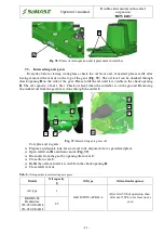
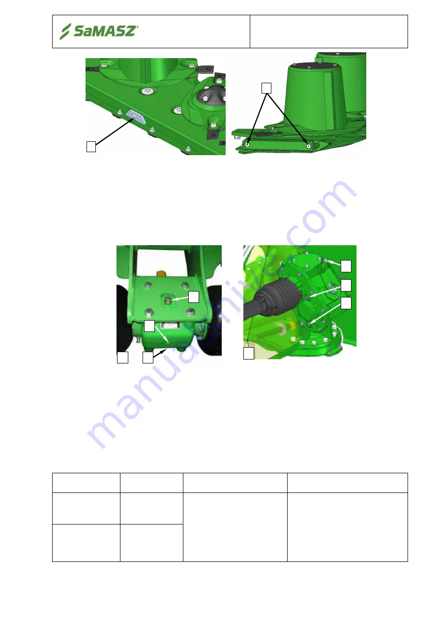
Fig. 38. 

Points of oil inspection and replacement in cutterbar 


7.3.


Intersecting axis gears 

Everyday  before  starting  work  please  check  the  oil  level  and,  if  needed,  please  refill  after 

having removed the vent 

A

 on the top of the gear (

Fig. 39

). The oil level can be checked through 

check opening 

B

 on the side of the gear. Please refill the oil until it is visible in the check opening 

B

. The oil capacity: about 1 liter. Check oil level when the cutterbar is on the ground. Removing 

the worked oil from the gearbox is done through the outlet 

C

.


Fig. 39. 

Intersecting axis gears oil 


To replace oil in gears: 


Prepare an adequate tank for waste oil to be disposed of at a specialized plant, 


Open refill vent 

and drain vent 

(

Fig. 39

), 


Drain oils from the gear by opening drain vent 

C


Close drain vent 

C


Refill the oil level until it is visible in the check opening 

B


Close refill vent 

A


Tab. 6. 

Oil capacities in intersecting axis gears


Model 

Oil capacity 

 [l] 

Oil type 

Orrication frequency 

All type 

SAE 80W/90, API GL-4 

After first 50 h of operation, then 

after next 500 h


(or at least once a 

year) 

KDDR S/SL 

Przekładnie:  

052-02.0100AB.L 
053-02.0100AB.L 

2,5 


a) 

b) 

A

Summary of Contents for KDDR 861

Page 1: ...w samasz pl INSTRUCTION MANUAL Double sided mower with central suspension REWERS KDDR 861 8 60 m KDDR suitable for KDF 300 KDF 340 KDF 301 S SL KDF 341 S SL KDDR 861 H 8 60 m KDDR 861 S H SL H 8 60 m...

Page 2: ...oven design with thousands of machines in regular use in many countries and quality materials ensure high durability and reliability of SaMASZ mowers We congratulate you on the purchase of your new Sa...

Page 3: ...5 3 Control panel for mowers with controller 23 5 3 1 Setting mower in transport position on headlands 24 5 3 2 Setting mower in vertical transport position 24 5 3 3 Changing language version of cont...

Page 4: ...UBRICATION 40 7 1 Risks present when lubricating 40 7 2 Cutterbar 40 7 3 Intersecting axis gears 41 7 4 Lubrication points 42 8 DEFECTS AND THEIR REPAIRS 43 9 DISASSEMBLY AND WITHDRAWAL FROM USE 44 9...

Page 5: ...s other basic equipment Operator s manual is attached to every machine in order that the operator can familiarize himself with design working principles service and adjustment of the mower The user o...

Page 6: ...fa on permanent grassland pastures on crop fields without rocks and to form loose rows of cut forage The pasture or field being mown should be even and best if prepared by rolling In the event there i...

Page 7: ...60 2 80 about 2 x 2 30 2 70 about 2 x 2 00 2 50 Weight of set with KDF 300 kg 3065 3040 4120 3840 3230 3130 4190 4040 Weight of set with KDF 340 kg 3145 3120 4200 3920 3310 3210 4270 4120 Weight of s...

Page 8: ...knives each Hydraulic lifting cylinder 2 fed from the tractor external hydraulics is used for moving the mower to working position Main frame with the cutterbar mounted is unloaded by springs 8 The KD...

Page 9: ...sing secured pins Fig 7 Fig 6 KDDR mower being operated as two sided mower Fig 7 Adjusting the mower for operation as two sided mower driving the tractor forward 3 2 1 KDDR mower with hydro pneumatic...

Page 10: ...arranty card operator s manual with catalogue of spare parts and declaration of conformity cutting knives 2 packages PTO shaft front hitch bracket 2 pcs spray paint 150 ml reflective plates with red l...

Page 11: ...shafts of other brands with equivalent parameters could be used after SaMASZ permission CAUTION Optional extra equipment should be ordered separately 4 SAFETY ADVICE 4 1 Safety rules and regulations...

Page 12: ...in Mower should not be operated when the tractor mower set is not balanced Never start the mower when it is lifted Never start the mower when people or animals are near the machine Never lift safety g...

Page 13: ...with the aggregate is likely Before any maintenance works set the machine on a stable ground and secure it against unintentional moving When cleaning the machine for health protection use personal pro...

Page 14: ...ort Front axis of the tractor should be weighted to keep the balance If needed use weights on front axis Every position change of the mower can only be done when there is nobody around pay particular...

Page 15: ...is no greater than 120 and the angle between the strand and the vertical is no greater than 60 collapsible parts should be blocked in transport position during putting the mower onto another vehicle i...

Page 16: ...tching the hoses when operating Do not allow hydraulic hoses to get deflected Do not expose hydraulic hoses to contact with any sharp edges If damaged or worn replace the hoses with new ones Useful li...

Page 17: ...erator s manual never operate the mower when it is not in working order or has damaged safety guards never get your hands and legs close to rotating parts of the mower during repair and maintenance of...

Page 18: ...haft is rotating N 02 Caution cutting knives Approach during operation is forbidden N 03 Read the operator s manual before putting the mower into operation N 04 While making repairs the machine must b...

Page 19: ...ile steering tractor s lift N 50 Do not stay in the swinging area of mower s parts N 52 Wear protective gloves N 55 N 63 N 109 N 96 for KDDR S SL N 117 Avoid fluid escaping under pressure Consult tech...

Page 20: ...WERS 18 N 162 N 224 Do not open and remove safety guards with motor operating Fig 12a Warning decals placed on the mower KDDR N 40 N 52 N 28 N 01 N 02 N 03 N 04 N 06 N 07 N 23 N 48 N 49 N 50 N 52 N 11...

Page 21: ...n protects mower against hitting small obstacles In the event of hitting an immovable obstacle the cutterbar folds back about 30 degrees and at the same time rises about 70 cm After that the cutterbar...

Page 22: ...he machine and the tractor Any accidental maneuvering with the set may cause to crushing of unauthorized personnel CAUTION The machine should be mounted on a level ground Mount the mower on the tracto...

Page 23: ...g it on the KDD lifter so that the distance between stopper O Fig 18 and mower s linkage is about 20 cm o Lock the adjusted height using links on the KDD mower Fig 18 Fig 18 Connect control panel usin...

Page 24: ...ames on two sided mower to transport or working position red hose 5 2 Mounting PTO shaft PTO shaft s end with overrunning clutch should be mounted on mower s side When connecting PTO shaft between tra...

Page 25: ...ator s manuals of both the machine and PTO shaft CAUTION When changing the tractor with which the machine operates control the length of PTO shaft again as otherwise the machine can be damaged 5 3 Con...

Page 26: ...ht one lift both of them to transport position on headlands using button 9 while using the lever to control the tractor s external hydraulics and lock the left one against falling with button 8 Right...

Page 27: ...ible to check the mower s serial number and work time i e machine s man hour time To run service mode turn off the panel and press buttons 1 and 2 at the same time until information is displayed on th...

Page 28: ...lowing devices Warning light plates fixed on the mower s or conveyors frame The panel comprises warning plate with combined lamp mounted parking stop lights and driving direction and with red reflecto...

Page 29: ...s lever lower the cutterbar to reach the horizontal position in a possibly slow way unblock the lock lower the mower until the cutterbar touches the ground fold side safety curtain using upper link C...

Page 30: ...E PRESSURE IN UNLOADING ASSEMBLY CAUTION Improper unloading of the mower s cutting unit will cause increased pressure of the bar onto the ground which may result in faster wearing of toppings overload...

Page 31: ...you have mowed with 2 drum mower you need a piece of essential information 1 Main advantage of disc mowers is their small power demand 20 less tractor power small moment of inertia and possibility to...

Page 32: ...the mowed grass is likely This slightly impairs the attractiveness of the stubble after having been mown however has hardly any impact on the mower s operation With inclination of the cutterbar to th...

Page 33: ...and remove the collected material using a sharp tool Once a blockage is removed check whether there are no damages to working elements 5 8 3 Taking turns over swaths When operating headlands lift cut...

Page 34: ...der shed houses etc the mower may be stored in vertical position Fig 28 but always on paved surface Storing the mower on an unpaved surface is inadmissible for it may cause the mower to lose stability...

Page 35: ...29 Mounting of the knives on mowing discs CAUTION Use only knives recommended by the manufacturer CAUTION Before any work always check the condition of knives knife mountings and holders Damaged or wo...

Page 36: ...ations of the mower which may indicate that the disc s operate with 1 cutting knife attached only Long term cutting with insufficient amount of knives will cause permanent damage to the cutterbar not...

Page 37: ...nual Double sided mower with central suspension REWERS 35 KDDR 861 right cutterbar KDDR 861 left cutterbar KDDR 941 right cutterbar KDDR 941 left cutterbar Fig 32 Rotating direction of disks in each t...

Page 38: ...sen locknuts 4 and screws 5 then adjust shield height and angle 7 tighten screws 5 and locknuts 4 Fig 33 Adjustment of swath guides 1 swath guide 2 locknuts 3 arm adjustment screws 4 locknuts 5 shield...

Page 39: ...ass there may be a necessity to adjust the mask of conditioner The higher and thicker grass the bigger the space between conditioner s mask and its shaft should be A proper setting should be done expe...

Page 40: ...When inspecting also not the condition of rubbers where flails are mounted applicable to shafts with rubber flail mountings If flails or bolts or rubbers are worn or damaged replace them Bear in mind...

Page 41: ...e by 10 if threads are oiled before assembly 6 7 Maintenance and service 6 7 1 Daily maintenance Every day after work please carry out the following maintenance check all visible units and parts and t...

Page 42: ...n lubricating protect skin against contact with the substance Therefore use adequate long sleeved protective clothing and protective shoes Use protective gloves too In case of a contact with skin imme...

Page 43: ...rbar is on the ground Removing the worked oil from the gearbox is done through the outlet C Fig 39 Intersecting axis gears oil To replace oil in gears Prepare an adequate tank for waste oil to be disp...

Page 44: ...rication points Every 50 hours of the mower s operation lubricate its joints Fig 40 using STP grease Bearings Fig 41 on the mower should be lubricated using T43 grease or other equivalent lubricant fo...

Page 45: ...too narrow Space swath guides to their maximum Safety device is working often without clear reason Worn elements of safety device or improper regulation This repair must be done by SaMASZ service Mow...

Page 46: ...arm up start to make sure the repaired machine operates properly CAUTION Before any repair works disconnect the machine from the tractor 9 2 Disassembly and withdrawal from use If the mower cannot be...

Page 47: ...ment are considered within 14 days by the manufacturer 5 The following cases are not covered by warranty a wearing parts cutting discs toppings sliding bushings gears and parts inside gears bushings a...

Page 48: ...g the service agreement caused by the user makes simultaneous breaching of the warranty 9 Manufacturer does not take compensation responsibility for the loss caused by breakdown of the machine during...

Page 49: ...ower with central suspension REWERS 47 11 2 Warranty repairs record Repairs description and changed spare parts Date stamp and signature of repair shop Date stamp and signature of repair shop Date sta...

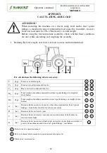
Page 50: ...tractor TT kg Rear axis load on unloaded tractor MP kg Total weight of machine mounted on front 3 point linkage or weight of front ballast MT kg Total weight of machine mounted on rear 3 point linkage...

Page 51: ...point linkage MT it is lighter than minimum required load at the rear so increase the weight of this machine to the required minimum load Calculating real axis load at tractor s rear axis TT rzecz Ty...

Reviews: