Operating manual
Rear disc mowers with central suspension
- with hydro-pneumatic or spring suspension
- 9 -
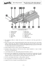
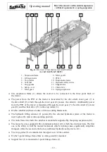
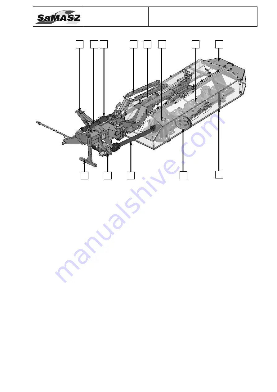
Fig. 3b. Overview of rear disk mower (narrow swath)
(On special order, for: KT 260, KT 300, KT 340)
1 – Suspension frame
2 – Lifting actuator
3 – Miter gear I
4 – Cutterbar
5 – Crop gatherers
6 – Safety cover
7 – PTO I
8 – Miter gear II
9 – Spring suspension
10 – Rotational actuator
11 – Hydraulic safety device
12 – Support foot
The suspension frame (1) allows the mower to be connected to the three point hitch of
the tractor.
The power from the PTO of the tractor is transferred by the drive shaft, the miter gear (3) to
the drive shaft (7), which through the miter gear (8) powers the cutterbar (4).
On the cutterbar (4) there are discs with two cutting blades each.
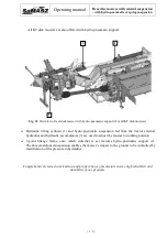
The hydraulic lifting actuator (2) powered by the external hydraulic system of the tractor is
used to place the mower into operating position. The main frame on which the cutterbar is
mounted is supported by the spring suspension (9).
The mower is also equipped with a rotational actuator (10), which has two functions. The first
one is the ability to fold the mower backwards which, in many cases, significantly simplifies
transport, while the second is the factory calibrated hydraulic safety device (11).
The crop gatherers (5) and safety cover (6) are also installed on the main frame.
Support foot (12) is mounted to 3-point linkage frame (1).
1
5
6
8
9
2
10 11
12
3
7
4
5

