background image

16

Vise

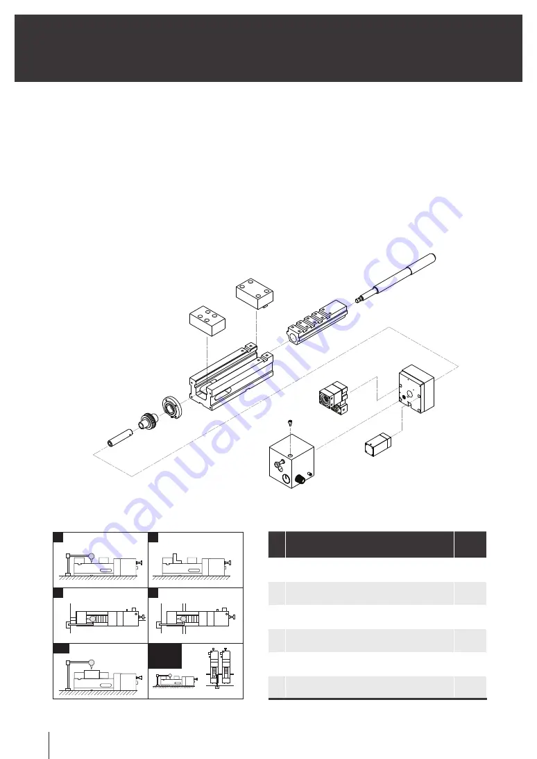
The following maintenance must be carried 
out at adequate intervals in accordance with 
operating conditions and frequency.

(1) Check the flatness of the bottom face of 
     vise so as to be free from damage and 
     dirt. Coat this face and upper face with 
     machine oil regularly.

(2) Clean vise and around.

(3) Clean T-shape slide way and clamp 
     screw. Coat them with high-pressure 
     grease. Optimal longtime PDI(Nippon 
     Perkerlizing Co.) is applied before
     shipping.

작동조건이나 빈도에 따라 적절한 주기로 보수
점검 해 주십시오.

(1) 본체 상면이 이물질에 손상되지 않았는지 
    확인하시고 사용시 오일을 공급해 주십시오.

(2) 제품 및 주변을 청결하게 사용해 주십시오.

(3) 스크류바와 T-홈 부에는 고압용 그리스를 
    사용해 주십시오.

5. Maintenance
    and inspection

5. 

维修

5. 유지보수

0.010

1

2

3

5, 6

4

병렬사양
Parallel use

并列规格

0.010

Fig.7

Fig.8

需要根据工作条件和频率,按适当周期定
期维修。

(1) 检查本体上面是否受异物损伤,然后
    照样使用。

(2) 清洁虎钳和周围。

(3) 丝杠和T槽要使用高压用润滑油。

정도규격 / Accuracy standard / 

精度规格

No.

검사항목

Inspection list

检查项目

허용치

Tolerance

允许值

1

몸체 밑면과 상면의 평행도

Parallelism between top and bottom face

本体底面与平行度

0.010

2

고정죠 및 이동죠와 몸체 상면과의 직각도

Squareness between jaws and top face

固定卡爪与移动卡爪跟本体上面的垂直度

0.010

3

몸체의 가이드 블록과 고정 죠와의 직각도

Squareness between guide block (key) and fixed jaw

本体的导块与固定卡爪的垂直度

0.015

4

몸체의 가이드 블록과 고정죠와의 평행도

Parallelism between guide block (key) and fixed jaw

本体的导块与固定卡爪的平行度

0.010

5

파악시 몸체와 테스트 블록과의 평행도

Parallelism between guide block (key) and body during 

clamping

夹持时本体与测试块之间的平行度

0.015

6

파악시 몸체와의 테스트 블록과의 부상량

Lifting between body and test block during clamping

夹持时本体与测试块之间的浮上量

0.015

Summary of Contents for APV-125

Page 1: ...understand DANGER WARN ING items in this maunal before operating the vise Please keep this manual by your side for answers to any questions you may have and to check IMPORTANT Air Vise Instruction Man...

Page 2: ......

Page 3: ...ol which emphasizes important information Warning term DANGER WARNING CAUTION IMPORTANT Indicates an imminently hazardous situation which if not avoided will result in death or serious injury These wa...

Page 4: ...4 Vise 1 7 2 10 2 2 10 3 11 4 13 4 1 13 4 2 13 4 3 15 5 16 6 17 7 18 8 20 9 21...

Page 5: ...ummary 10 2 2 Construction and operation 10 3 Mounting 11 4 Precautions 13 4 1 Clamping force setting 13 4 2 Workpiece clamping 13 4 3 Clamping range of work 15 5 Maintenance and inspection 16 6 Troub...

Page 6: ...6 Vise 1 7 2 10 2 2 10 3 11 4 13 4 1 13 4 2 13 4 3 15 5 16 6 17 7 18 8 20 9 21...

Page 7: ...e may be thrown from the chuck Incorrect Correct Danger by discharge of chuck or workpiece in case of damaging of vise DANGER Switch power off before setting inspecting or changing the vise Loose clot...

Page 8: ...the influence lowers judgment and increases likelihood of accident Loose clothing may be caught in the machine Alcohol Drugs NO NO NO L2 L1 2 L2 L1 2 The height of the workpiece should be lower than t...

Page 9: ...he vise use an eyebolt and wire rope When gripping workpiece make sure your hand is clear from the gripping area Thoroughly clean the vise The vise may fall and cause injury Dirt and debris will affec...

Page 10: ...uates the piston and allows the jaws to clamp to the adjusted torque The sliding jaw s air actuated travel is 8mm The sound during clamping is due to air exhaust mm Jaw width mm mm Air vise APV 125 2...

Page 11: ...efore mounting 3 Carefully position when using T groove 4 Securely fix the vise into the machine tool with attached clamp device Clamp devices are attached 1 2 3 T 4 IMPORTANT IMPORTANT Push the guide...

Page 12: ...Torque Bolt Size Tightening Torque M10 72 6N m 7 4kgf m M16 250 0N m 25 5kgf m M12 106 8N m 10 9kgf m M20 402 1N m 41 0kgf m M14 170 6N m 17 4kgf m M22 539 4N m 55 0kgf m IMPORTANT IMPORTANT Adjust th...

Page 13: ...3 4 5 6 7 0 Total gripping force kgf bar 1 000 2 000 3 000 4 000 5 000 6 000 1 2 3 4 5 6 7 Fig 5 Clamp Adjust the clamping force through the regulator pressure Adjust distance between workpiece and ja...

Page 14: ...work piece The workpiece is off center Use jaws suitable to the work piece Not enough clamping depth Use as much depth as possible Unilateral clamping Clamp concentrically Lower part of workpiece is...

Page 15: ...0 3 0 56 4 1 000 2 000 3 000 4 000 1 2 3 4 5 6 bar kgf 7 1 2 ISO VG32 3 4 8mm 8mm 5 Max 6kgf cm2 OIL HOLE 4 3 2 1 Adjust the clamping range with using grooves APV 125 APV 160 0 65 3 65 115 2 115 165 1...

Page 16: ...ure grease Optimal longtime PDI Nippon Perkerlizing Co is applied before shipping 1 2 3 T 5 Maintenance and inspection 5 5 0 010 1 2 3 5 6 4 Parallel use 0 010 Fig 7 Fig 8 1 2 3 T Accuracy standard No...

Page 17: ...ut off pressure source Fig 9 VG 32 Fig 9 Poor accuracy Incorrect mounting Page 11 Follow the recommended mounting method Page 11 Page 11 Mounting surface is not level or the workpiece is not completel...

Page 18: ...mm JAW Jaw height mm Max opening mm Total height mm Slider height mm Total width mm Total length mm Max gripping force KN kgf Weight kgf APV 125 125 50 188 150 100 166 585 35 3500 55 Type A B C D E F...

Page 19: ...AW Jaw width mm JAW Jaw height mm Max opening mm Total height mm Slider height mm Total width mm Total length mm Max gripping force KN kgf Weight kgf APV 160 160 60 165 160 100 199 584 60 6000 63 Type...

Page 20: ...ulator 1 14 Coupler 1 No Name Q ty 15 Oil plug 1 16 Movable jaw 1 17 Fixed jaw 1 18 Hex Socket head bolt 4 19 Hex Socket head bolt 4 20 Name plate 1 21 Handle 1 22 Eyebolt 2 23 Hex Socket head bolt 2...

Page 21: ...21 Instruction Manual mm 9 Accessories 9 9 Type Wrench bolt T T nut T Wsher Guide block Body fixer Handle APV 125 M16X65 M16 16X3 0T 25X18X10 45X30 5X77 14 APV 160...

Page 22: ...n o t e...

Page 23: ...n o t e...

Page 24: ...n o t e...

Page 25: ......

Page 26: ......

Page 27: ......

Page 28: ...te st e d P ro d u kt io n u b er w ac h t B au ar t g ep ru ft s ISO 9001 2008 A P V Air VIse APV Instruction Manual APV Samchully Machinery 405 820 55 TEL 82 32 822 4811 FAX 82 32 822 4377 405 820 5...

Reviews: