14
15
NC Rotary Table
Instruction Manual
3.
정밀도 / Accuracy
1
2
3
4
5
6
8
9
7
테이블 기준경의 흔들림
테이블 윗면의 진직도 (센터에서 약간 낮게)
테이블 윗면의 평행도
주축 중심선과 기준면과의 평행도
테이블 윗면과 기준면과의 직각도
회전시 테이블 흔들림
센터높이
위치정밀도
반복정밀도
검 사 사 항
/ Test Item
허용치
/ Tolerance
0.020
HRS-174
HRS-174F2
HRS-204
HRS-204F4
HRS-254
HRS-254F4
HRS-254F8
HRS-324
HRS-324F8
0.020
0.020
0.020
0.020
0.020
H=
±0.020
20 sec
4 sec
(단위 / Unit : ㎜)
8,9
1
2
4
5
6
7
3
측정장치에 의해 실시한다. /
This work shall be conducted with a measuring instrument.
[ 표 / Table 2 ]
[ 그림 / Fig 1 ]
Center hole run-out at Table
Run-out of Table face in rotation
Squareness between Table face and Base
at Table Dia.
Parallelism between Center of hole and Base
Center Height
Indexing accuracy
Repeatability
Flatness of Table face
Parallelism between Table face and Base
4.
운전 준비 / Preparations for Operation
4-1 설치
4-1 Installation
4.1.1. 운반과 공작기계에의 장착
4.1.1. Transportation, and Installation
on the Machine Tool
!
WARNING
경 고
!
WARNING
경 고
!
WARNING
경 고
!
WARNING
!
WARNING
!
WARNING
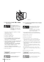
포장상자를 열고 공작기계에 장착하여 운전에 들어가기 전 다음의 모든
점에 주의하여 준비 및 시운전을 해주십시오.
1) 운반은 부속의 아이볼트에 강도가 충분한 로프를 걸고 충격을 주지
않도록 신중하게 행하여 주십시오.
2) 공작기계의 테이블면 NC 로터리 테이블의 설치기준면에 날카로운
부위나 흠집이 없는 것을 확인하며 청소해 주십시오.
날카로운 부위가 많거나 흠집 등이 있는 경우에는 수정하여 부착해
주십시오.
3) 작업에 가장 적합한 위치에 설치해 주십시오. 세로설치용 설치기준면의
가이드블록을 공작기계의 테이블 홈에 끼워 넣습니다. T홈부와
가이드블록과의 틈이 큰 경우에는 T홈부의 한쪽으로 가까이 붙여
설치해주십시오.
4) 클램프 기구를 사용하여 NC 로터리 테이블을 공작기계에 단단하게
고정해 주십시오.
NC 로터리 테이블을 공작기계에 설치할
경우에는 설치 스페이스를 잘 확인하여
설치해 주십시오. 특히 공작기계의 테이블
또는 스핀들헤드 등이 이동하여 공작기계의
스플래시가드 또는 ATC장치, 스핀들헤드
등에 NC 로터리 테이블 본체 및 케이블,
에어호스 등이 간섭되지 않도록 주의해
주십시오.
케이블은 손상되거나 무리하게 걸거나 또는
무거운 물건을 올려놓거나 복잡하게 틈에
끼우지 마십시오. 케이블이 손상되면 감전될
염려가 있습니다.
설치자리를 유효하게 확인하고
클램프기구의 볼트를 규정 토크로 조여
주십시오.
1) For transportation, lift with a strong rope using the eye
bolts. Move carefully so as not to subject the product to
shock or impact.
2) Inspect the surface of the table of the machine tool and
the reference plane for the installation of the NC Rotary
Table to see whether there are any sharp protrusions or
flaws. Correct/remove such flaws, if any. Clean the any
foreign material from the surfaces before installation.
3) Install the product on the machine tool at the most
convenient position for work. Insert the guide block of the
longitudinal installation reference plane into the groove in
the table of the machine tool. If the gap between the
T-groove of the table and the guide block is excessive,
position the block close to one side of the T-groove.
4) Fix the NC Rotary Table to the machine tool firmly using
the accessory clamp device.
When installing an NC Rotary Table
on a machine tool, check the
installation space carefully. Take care
that the main body, cable, and
air-hose of the NC Rotary Table do
not interfere with the splash guard,
ATC device, or spindle head when
the table or spindle head of the
machine tool moves.
Do not use damaged cable, or apply
excessive stress. Do not lay a heavy
object on the cable or insert into a
complicated groove. Damaged cable
may cause electric shock.
Check the available space for
installation. Tighten the bolt of the
clamp mechanism to the specified
torque.
Unpack the delivered product, and conduct the following
preparations and tests before installing it on the machine
tool for production.


