14
Rotary Cylinder
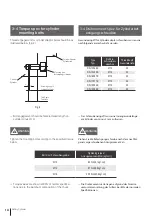
The “L” dimension can be found by the above table
when the distance A between the cylinder adaptor and the
chuck mounting face is given.(Fig.4-1)
Die “L”-Dimension kann aus der vorstehenden Tabelle
entnommen werden, wenn der Abstand A zwischen dem
Zylinderteil und der Spannfuttermontagefläche bekannt
ist. (Abb.4-1)
z.B.) Wenn der Abstand A (zwischen Zylinderadapter und
Rückwand) im Falle von HS-06 und SH-13046 800 mm
beträgt, wird die Gesamtlänge des Ziehrohrs wie folgt
betragen.
L = A + 41 = 800 + 41 = 841 mm
●
Ein akkurates Gewinde muss auf dem Ziehrohr in
Übereinstimmung zur Verfügung gestellt werden.
Stellen Sie sicher, dass die Härte des Ziehrohrs ausreichend
ist. Schäden am Ziehrohr, die aufgrund unzureichender
Härte auftreten, können das Risiko mit sich bringen, dass
das Werkstück aus dem Spannfutter geschleudert wird.
!
WARNUNG
Make sure the draw pipe hardness is adequate. Damage
to draw pipe due to insufficient hardness will risk the work-
piece being thrown from the chuck.
!
WARNING
Ein Lösen der Gewinde während des Betriebs kann
Schwingungen verursachen und das Ziehrohr schwächen.
Gewinde-D, F muss konzentrisch innerhalb von 0,05 mm
T.I.R. sein
WICHTIG
Loosening of threads during operation can cause vibration
and weaken the draw pipe. Thread D, F should be concen-
tric whithin 0.05mm T.I.R.
IMPORTANT
ex) When the distance A (between cylinder adaptor and
back plate) is 800mm in case of HS-06 and SD-13546
the overall length of the draw pipe will be as follows.
L=A+41= 800 + 41 = 841mm
● Accurate threading must be provided on the draw
pipe in conformity.
Summary of Contents for SD-E
Page 2: ......
Page 31: ...31 Instruction Manual n o t e...
Page 34: ...34 Rotary Cylinder Fig 14 21 26 19 20 23 25 18 17 22 16 15 24...
Page 41: ...n o t e...
Page 42: ......
Page 43: ......


