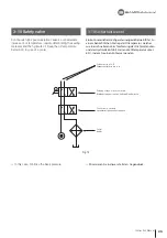
+
+
V
+
DC10~30V
+
V
OP1
OV
OP2
OV
-
-
+
37
Instruction Manual
Terminal connections /
Klemmenbelegung
Specification /
Technische Daten
PR12-2DP
(AUTONIX)
OP2
WHITE
WEISS
+V
RED
ROT
OV
BLACK
SCHWARZ
OP1
WHITE
WEISS
Der Näherungsschalter ist am Rahmen durch die Stellplatte
montiert und muss mit den Schrauben des Näherungss-
chalters und der Stellplatte so eingestellt werden, dass
der Abstand zwischen dem Ende des Sensorrings ca. 1mm
beträgt. Die Einstellung der axialen Richtung erfolgt durch
ein Verschieben der Stellplatte. Der Näherungsschalter kann
mittels der LED auf dem Schalter überprüft werden.
The proximity switch is mounted to brackets through the
adjusting plate and must be set with the screws of the
proximity switch and the adjusting plate so that the dis-
tance between the end of the sensor ring is approx. 1mm.
The adjustment to the axial direction is done by sliding the
adjusting plate. The proximity switch can be checked with
the LED on the switch.
Adjusting the position
of a proximity switch
Das Einstellen der Position eines
Näherungsschalters
Fig.15
Output /
Ausgang
Output /
Ausgang
Load /
Last
Load /
Last
Summary of Contents for SD-E
Page 2: ......
Page 31: ...31 Instruction Manual n o t e...
Page 34: ...34 Rotary Cylinder Fig 14 21 26 19 20 23 25 18 17 22 16 15 24...
Page 41: ...n o t e...
Page 42: ......
Page 43: ......

