background image

19

Instruction Manual

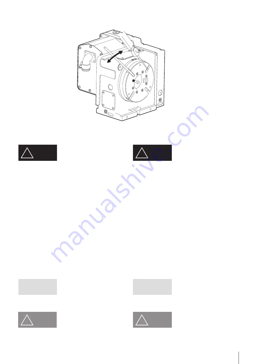
1)  조정하기 전에 테이블의 공작물, 지그 등을 제거하고 테이블의 수평을 맞

추십시오. (그림 6)

2) 배출구에서 윤활유를 제거합니다.
3) ①HOUSING COVER를 제거합니다.
4) ②HOUSING PLUG를 제거합니다.
5)  ③HOUSING 정면에 체결된 ④SETSCREW 3개소를 느슨하게 풀고 

③HOUSING 정면에 체결되지 않은 곳에 BOLT를 2개소 부분에 체결합니
다. (HOUSING 회전에 필요)

6)  ③HOUSING에 체결한 BOLT를 손으로 잡고 회전하여 백래시량을 조정

한 후 ⑤WORM SHAFT 육각 홈 부분에 T-WRENCH를 삽입하여 백래시
량의 정도를 확인합니다. (참고: 백래시량 측정방법은 본 설명서 18 Page 
WORMGEAR BACKLASH 조정법에 기재되어 있으니 확인하시기 바랍니
다. 백래시는 시계방향으로 회전할수록 작아집니다.)

7)  백래시 조정이 완료되면 ③HOUSING 전면에 체결된 ④SETSCREW 3개

소를 완전히 잠그고 BOLT 2개소 제거합니다.

8) 백래시 조정을 종료합니다.

1)  Before adjusting backlash, remove the workpiece and jig from the 

table, and set the table in horizontal position. (Fig 6)

2) Remove lubricant from the exit.
3) ①Remove the housing cover.
4) ①Remove the housing plug.
5)  Loosen three ④screws on the front of the ③housing. Install bolts 

into the two taps on the front of the ③housing where there is no bolt 
(Required for turning the housing).

6)  Adjust the backlash by turning the housing ③with the bolts using 

hands. Insert a T-wrench into the hexagonal recess of the ⑤worm 
shaft. (Note: refer to Worm Gear Backlash Adjustment, page 18 of 
this manual. The backlash is reduced when the housing is turned 
clockwise.)

7)  When the backlash has been adjusted, tighten the three ④screws on 

the front of the ③housing, and remove the two bolts.

8) Backlash adjustment is completed.

7.1.2 웜 기어 백래시 조정

7.1.2. Adjusting backlash of worm gear

IMPORTANT

유의사항

HOUSING을 시계방향(CW)으로 1회전하면 백래시는 작아집니다.

백래시 조정을 할 경우에는 반드시 제어장치의 전원을 OFF, 또한 NC 로터리
테이블을 언클램프 상태로 한 후에 조정해 주십시오. 회전중에 잘못하여 손
이나 의복이 기어에 닿으면 말려들어가 큰 사고로 연결될 염려가 있으니 주
의하십시오.

IMPORTANT

The backlash is reduced when the housing is rotated by on turn 
clockwise.

When adjusting backlash, the power of the controller must be turned 
off and the NC Rotary Table must be unclamped. Your body or clothes 
can be caught in the machine during rotation, which leads to a serious 
accident.

!

DANGER

위 험

!

DANGER

!

CAUTION

주 의

백래시를 성급하게 조정하지 마십시오. 천천히 조심스럽게 조정하십시오.

!

CAUTION

Do not adjust the backlash abruptly. Adjust it slowly and carefully.

[ 그림 / Fig.5 ]

Summary of Contents for SR-200

Page 1: ...Maunted Series Instruction Manual SR 200 SR 250 1 Please read the DANGER and Warning sections before operating the NC Rotary Table Please keep this manual handy as it may answers to any questions you...

Page 2: ...2 NC Rotary Table...

Page 3: ...tion Warning term DANGER WARNING CAUTION IMPORTANT DANGER WARNING CAUTION IMPORTANT Indicates an imminently hazardous situation which if not avoided will result in death or serious injury These warnin...

Page 4: ...14 4 3 1 Air Clamp System 1 4 4 4 Air Purge System 15 4 5 15 5 16 5 1 16 5 2 16 6 16 6 1 NC Rotary Table Clamp 16 6 2 Clamp Unclamp 17 6 3 Clamp Unclamp Solenoid Valve 17 7 18 7 1 18 7 1 1 Worm Gear B...

Page 5: ...ion 1 6 5 2 Periodic Inspection 1 6 6 Description of the NC Rotary Table 16 6 1 Cautions for the Table Clamp 1 6 6 2 Clamp Unclamp Check Device 1 7 6 3 Solenoid Valve for Clamp Unclamp 1 7 7 Descripti...

Page 6: ...machinery and the controllers for installation prior to start installation maintenance or repair of the tilting NC rotary table Loose clothing or limbs may get caught during operation Tighten the bol...

Page 7: ...y workpieces Damage may occur Excessively long or heavy workpieces may result in them being thrown from the rotary table NC Do not exceed the allowable cutting force Product may be damaged and or work...

Page 8: ...Use eyebolts and wireropes when moving the NC rotary table Dropping the rotary table will cause damage and possibly injury CAUTION CAUTION 6 NC Change the lubricant every six months Actual change cycl...

Page 9: ...ompressed air through the air combination lubricator mist separator regulator drain the com pressed air inlet is located on the motor case Drain air filter regularly an auto drain system is recommende...

Page 10: ...earance drawing The maximum table rotation speed is the value at Motor 3000min In order to meet the specifications of the motors attached with absolute encoders the starting point origin of the machin...

Page 11: ...value Model 1 Run out of Table face in rotation 0 020 SR 200 SR 250 2 Parallelism between center of hole and Base 0 020 3 Squareness between Table face and base 0 020 at Table Dia 4 Center hole run ou...

Page 12: ...he gap between the T slot and the guide block is large install the product close to either side of the T slot 4 Use a clamping device to securely fasten the NC rotary table to the machine tool 4 1 1 4...

Page 13: ...he old oil and do not allow any debris of foreign material to enter the tank If contaminated with foreign material the bearings may become stuck and accuracy may diminish Use the following lubricant R...

Page 14: ...oil dust removed page 9 2 Connect the air hose to the air inlet The air inlet PT 1 4 is located on the motor casing See the outside drawing for installation 3 The supply pressure of the air should be...

Page 15: ...thus air pressure is applied to the motor cover As such the air exit must be kept open When the air is discharged out the operator can hear the sound The hydraulic clamping system requires an addition...

Page 16: ...amaged cable 3 Corrosion open circuit in the motor casing CAUTION CAUTION CAUTION The Rotary Table must be rotated while unclamped and processing after positioning must be performed while clamped Inco...

Page 17: ...g are as follows which must be taken into consideration into the electric wiring Solenoid ON table unclamp Solenoid OFF table clamp 6 2 6 2 Clamp Unclamp Check Device 4 To prevent mistakes be sure to...

Page 18: ...eration is less than the optimal value due to thermal expansion Worm gear will not move if backlash is excessively low Measure backlash before adjusting CAUTION CAUTION Appropriate Backlash 1 T SOLT 2...

Page 19: ...using hands Insert a T wrench into the hexagonal recess of the worm shaft Note refer to Worm Gear Backlash Adjustment page 18 of this manual The backlash is reduced when the housing is turned clockwis...

Page 20: ...eripheral devices of the table to confirm that the adjustment is satisfactory HOUSING PLUG O RING O RING OIL CAUTION When installing the housing plug take care not to damage the O ring Fig 6 IMPORTANT...

Page 21: ...o motor please be careful O ring is not lost or damaged there is o ring so that foreign matter does not enter 5 After disassembling Key and ring is decomposed with gear replace the motor 6 Assemble th...

Page 22: ...and cutting fluid from the Table completely and put it on rigid wooden plate to maintain accuracy Apply rust preventive oil to the Table and case or protect them with a wooden cover or wrap them with...

Page 23: ...mulated pitch error of 0 05 with Equation 2 yields Therefore the angle is 206 seconds or three minutes and 26 seconds As illustrated above the lengths and the angles of the peripheral devices are conv...

Page 24: ...8 C1 706 Samchully Machinery 405 820 99 TEL 032 822 4811 FAX 032 822 4377 405 820 99 Namdong daero Namdong gu Incheon TEL 82 32 899 8965 FAX 82 32 721 7607 1544 3122 NC NC Rotary Table Rear Maunted Se...

Reviews: