Assembly and commissioning
Page 28/55
13.
Connect the high voltage generator to the des-
ignated terminals.
Use the circuit diagrams from the beginning of
this chapter.
Connect the 230 V power supply to the ventila-
tion system.
Also use the circuit diagrams from the begin-
ning of this chapter.
Check the mounted protective earthing for
faultless function.
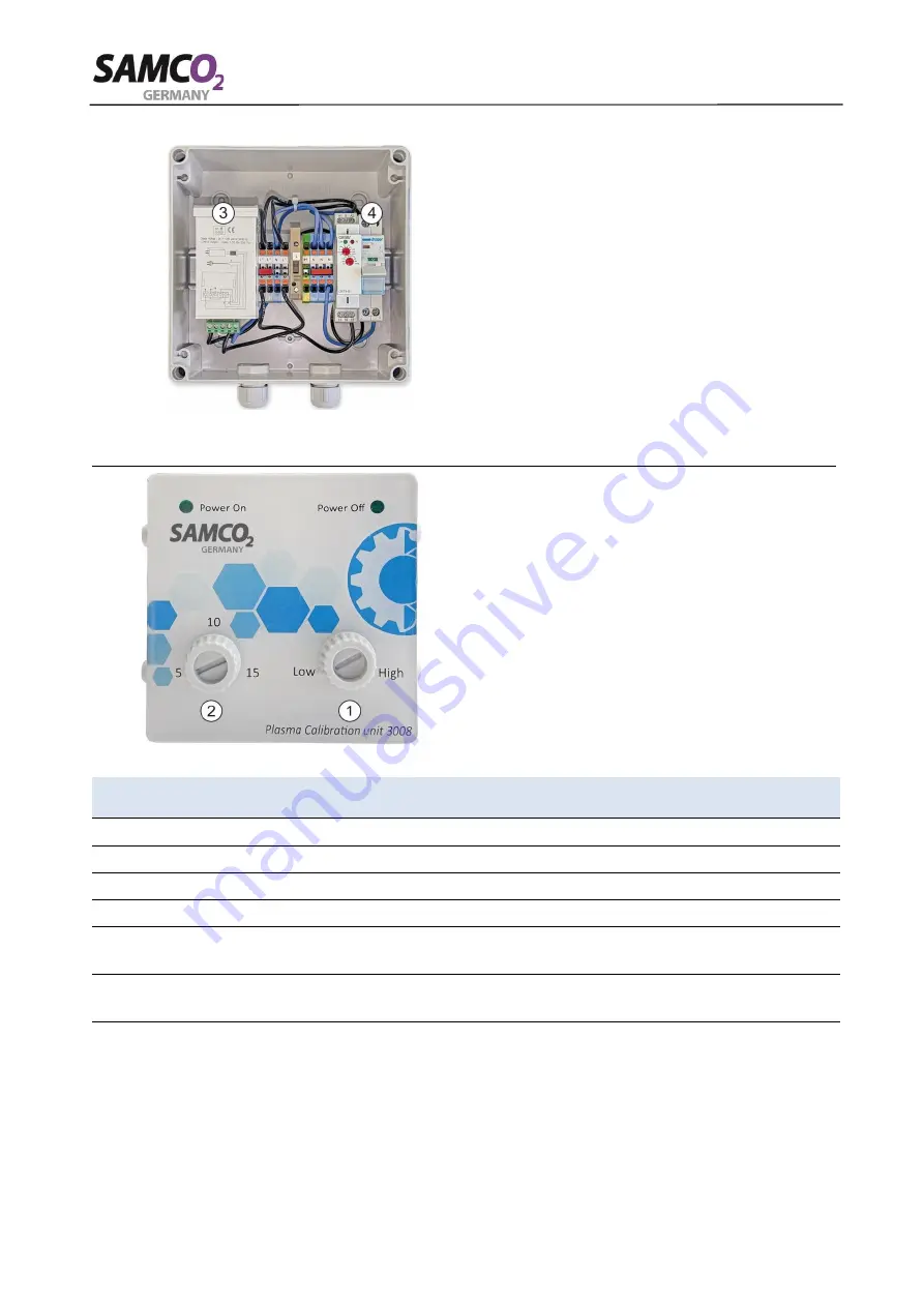
Set the timer (3) to your room size (see the fol-
lowing point).
Switch on the control unit at the mains switch
(4).
14.
Use the following table 6 for the correct set-
ting.
Use the controls for Timer 1 (1) and Timer 2
(2) to adjust.
Correct any faults that may have been found
and check again that they are functioning cor-
rectly.
Close the control unit.
Minimum
room size
Maximum
room size
Timer 1
Timer 2
Note
125 m
3
165 m
3
LOW
15
In rooms WITHOUT supply air system
*
165 m
3
210 m
3
LOW
10
In rooms WITHOUT supply air system
*
210 m
3
255 m
3
HIGH
15
In rooms WITHOUT supply air system
*
255 m
3
300 m
3
HIGH
10
In rooms WITHOUT supply air system
*
125 m
3
210 m
3
LOW
5
In rooms with legally designed supply
air/exhaust air system
210 m
3
300 m
3
HIGH
5
In rooms with legally designed supply
air/exhaust air system
*
The
use of the module does not replace the legal requirements for fresh air supply.
Table 6, Timer settings for room size
This completes the assembly of the module.


