background image


Spare parts


26/05/2020 


582115110-EN-indC-Pump-01D140-01D140E.docx


60 


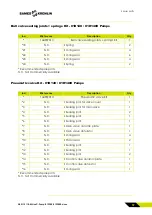
Pneumatic valve sealing joints Kit - 01D140 / 01D140E Pumps 


Ind. 

#Reference 

Description 

Qty 

*- 

144907018 

Pneumatic valve sealing joints Kit 

*2 

N.C. 

 Sealing joint for valve cover 

*3 

N.C. 

 Sealing joint for main valve 

*4 

N.C. 

 Sealing joint 

*5 

N.C. 

 Sealing joint 

*6 

N.C. 

 Sealing joint 

*9 

N.C. 

 O-ring seal 

*10 

N.C. 

 Piston seal 

*11 

N.C. 

 Sealing joint 

*12 

N.C. 

 Sealing joint 

*13 

N.C. 

 Sealing joint 

*16 

N.C. 

 O-ring seal 

* Recommended spare parts 

N.C. Not Commercially Available 


Summary of Contents for 01D140

Page 1: ...h IIB T6 T4 Gb X II 2 D Ex h IIIC 85 150 C Db X Equipment references 01D140 144907010 01D140E 144907015 User Manual 582115110 2020 05 26 Index C SAMES KREMLIN SAS 13 Chemin de Malacher 38240 Meylan w...

Page 2: ...whatsoever and any exploitation or communications of its contents are prohibited except with the express written consent of the manufacturer The descriptions and features contained in this document a...

Page 3: ...S 12 Material recommendations 12 Products implemented 16 2 ENVIRONMENT 18 Material marking 19 3 PRESENTATION OF THE EQUIPMENT 20 Context ofuse 20 Non intended use 20 Foreseeable misuse 21 4 IDENTIFICA...

Page 4: ...CINGPUMP COMPONENTS 48 11 1 REPLACING THE DIAPHRAGM 48 11 2 REPLACEMENT OF THE PNEUMATIC VALVE 49 11 2 1 DISMANTLING OF THE PNEUMATIC VALVE 50 11 2 2 MOUNTING THE PNEUMATIC VALVE 51 11 3 REPLACING THE...

Page 5: ...SEGUIN 01D140 01D140E Pumps B 26 05 2020 E DUMONT F SEGUIN Pumps 01D140 01D140E C 13 08 2019 Dear customer you have just purchased your new equipment and we thank you for it We have taken the utmost...

Page 6: ...see and appreciate The warranty excludes wear parts deterioration or wear resulting from abnormal or unscheduled use by SAMES KREMLIN failure to observe instructions for proper operation or lack of m...

Page 7: ...orm the material Parts and accessories must only be supplied or approved by the manufacturer Never operate the pump while damaged The equipment must be checked periodically Defective or worn parts mus...

Page 8: ...n authorised by the person responsible for safety to perform the respectively required tasks Personnel must be capable of recognising and avoiding possible dangers The required personnel qualification...

Page 9: ...ures of the equipment components Stay away from moving parts Danger of pressure Safety requires that a decompressed air shutoff valve be mounted on the pump motor supply circuit to allow trapped air t...

Page 10: ...jury To avoid these risks especially when using pumps it is imperative To connect the equipment the parts to be treated the cans of products and cleaners to the ground To ensure good ventilation Keep...

Page 11: ...be used in appropriate areas Contain the product used in the application in a container designed for that purpose Evacuate the products in accordance with the legislation of the country where the equi...

Page 12: ...ectors are put in place for safe use of the equipment Examples Engine hood Coupling protector Carters The manufacturer can not be held responsible in case of Bodily injury As well as breakdowns and or...

Page 13: ...this movement must be kept clean Before starting up or using the motor pump carefully read the DECOMPRESSION PROCEDURE Check that the decompression and purge air valves are working properly It is forb...

Page 14: ...air equipment variable pressure depending on the length of the pipes Rinsing the pump Wearing PPE glasses gloves safety shoes Do not look at the gun nozzle when it is under pressure Rinse at a maximum...

Page 15: ...140 F or below 0 C 32 F Do not use hoses to pull or move equipment Tighten all connections hoses and connectors before commissioning the equipment Check hoses regularly replace them if damaged Never...

Page 16: ...compatibility of materials is the responsibility of the user The user will have to identify and prevent the potential dangers inherent to the implemented products such as Toxic vapors Fire Explosions...

Page 17: ...ound absorber Depending on the pumped medium the sound absorber must be replaced by a suitable pipe or hose connection to avoid danger The outlet is to be removed to a safe place If diaphragms are com...

Page 18: ...re vibrations moving equipment etc where damage to the grounding function is likely the user will have to replace the wire of 2 5 mm supplied by a device more adapted to its environment wire of greate...

Page 19: ...ufacturer the reference of the device important information for the use of the device pressure power and sometimes against the pictogram shown below The equipment is designed and manufactured with hig...

Page 20: ...e other than the use described in the paragraph Intended use and in this operating manual and any use that extends beyond the specified intended use shall apply as non intended use The manufacturer sh...

Page 21: ...through a person qualified for that purpose The conveyance of media chemically incompatible with the materials used for the construction of the pump The operator of the pump must check the chemical co...

Page 22: ...on of the marking of the plate The nameplate affixed to the pump must not be removed and must be kept in a readable state in all circumstances This equipment complies with the following provisions Mac...

Page 23: ...Identification 582115110 EN indC Pump 01D140 01D140E docx 26 05 2020 23 Pump model 01D140E...

Page 24: ...uropean standards h Mode of protection for non electrical device IIB Reference gas for equipment qualification T6 T4 Temperature class Maximum surface temperature 85 C 135 C 185 F 275 F The actual max...

Page 25: ...e temperature for the explosive dust area The actual maximum surface temperature does not depend on the device but on the operating conditions medium temperature and compressed air temperature Db Equi...

Page 26: ...these processes Possible measures include filling the pipes and pump chambers with inert gas during dry operation slow filling and emptying of the pump safe avoidance of dry operation snore mode High...

Page 27: ...essed air temperature must be safely adjusted with sufficient difference below the ignition temperature of the potentially explosive atmosphere Ignition sources in the device Mechanically generated sp...

Page 28: ...height dry 3 50m max Maximum conveying output 60 l mn max at 6 bar 87 02 psi outlet open water Operating pressure 8 bar max 116 psi max filtered acc to DIN ISO 8573 Max viscosity of conveyed product 1...

Page 29: ...General specifications 582115110 EN indC Pump 01D140 01D140E docx 26 05 2020 29 Dimensions...

Page 30: ...he movement of the pump chamber the outlet valve closes and the inlet valve opens so that the liquid is sucked into the pump chamber When the diagram is moving in another direction the pump chamber be...

Page 31: ...dditional easily accessible shut off valve must be installed in front of the compressed air connection The pump must be integrated into the compressed air system so that it can be put out of operation...

Page 32: ...from further damage Use the packing slip to verify the completeness of the delivery Environment The pumps are designed to be installed in a paint booth Preparation WARNING Trained personnel with PPE m...

Page 33: ...onveyed Check if additional shut off valves need to be installed 2 Provide a compressed air hose from the compressed air source to the pump The plug connector 1 of the pump is 8 mm see technical chara...

Page 34: ...the pump housing Make sure to observe these arrows do not remove them and keep them in a clearly recognisable condition 7 Connect the suction hose to the inlet point 2 8 Connect the conveying hose to...

Page 35: ...storage after it has been thoroughly cleaned Extreme storage conditions accelerate the ageing process We recommend a storage temperature between 10 C 50 F and 25 C 77 F The diaphragms must not be exp...

Page 36: ...t to leak This may lead to the formation of an explosive mixture The conveying of explosive media and the employment in an explosion hazardous area is only permitted according to regulations by Direct...

Page 37: ...onveying capacity of the pump is converted into heat In case of short lines this can lead to dangerous heating of the medium Operation of the pump can adiabatically compress potentially explosive gas...

Page 38: ...son qualified for that purpose If the pump is not mounted on a horizontal even surface with the pump foot at the bottom vent the pump chambers Adjust the air pressure to 1 14 5 psi 8 bar 116 psi The p...

Page 39: ...the pump delivery rate is to be regulated the operating company must install a throttle valve in the compressed air supply or in the conveying line To reduce the delivery rate Reduce the compressed a...

Page 40: ...medium or does not stop when the pressure side is isolated Valves contaminated Flush pump with a cleaning agent Conveying hose blocked Clean conveying hose Suction and pressure valves contaminated All...

Page 41: ...ressure at the injection point too high Reduce back pressure at the injection point Screwed joints ball valve or non return valve have no or restricted clearance Restore clearance clean or replace Air...

Page 42: ...qualified personnel Wear personal protective equipment PPE WARNING Hazard to persons due to trapped compressed air and pressurized medium Do not maintain or clean the pump hoses or outlet valve while...

Page 43: ...ressure can remain in the pressure chamber causing medium to squirt out Please observe the safety data sheets of the previously conveyed chemicals when performing disassembly work on the pump Dependin...

Page 44: ...of the pump We therefore recommend regular inspection of the pump and the pneumatic valve Should a malfunction nonetheless occur or the conveying output decrease you can simply carry out the followin...

Page 45: ...luids media squirting out Cleaning repairs troubleshooting activities and fault elimination during which contact with the medium is possible may only be carried out when the relevant personal protecti...

Page 46: ...g agents must not be used at temperatures exceeding 65 C 149 F 2 Connect the suction line connection to the cleaning agent 3 Connect the medium outlet to a suitable container 4 Pump the cleaning agent...

Page 47: ...ior to decommissioning 1 Clean and empty the pump as described in the previous section 2 Renew the pump diaphragm at the latest after one year to ensure safe and reliable function of the pump as it is...

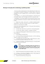
Page 48: ...ousing covers B and remove the housing cover B 2 Remove the diaphragm 1 from the piston rod by turning anticlockwise 3 Tightly screw the new diaphragm 1 in clockwise direction on to the piston rod 4 M...

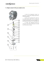
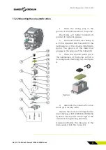
Page 49: ...e hexagonal head set screws A on the base plate B and remove the base plate B 2 Take out in sequence the seal 2 the intermediate plate C the O rings 4 and 5 the seal 3 the ceramic plate 7 the O ring 6...

Page 50: ...11 12 and 13 from the grooves in the pneumatic valve block E 2 Remove the covers F and O rings 9 3 Take out the slide G with the piston seals 10 from the pneumatic valve block E 4 Clean the component...

Page 51: ...the centrepiece of the double diaphragm pump The groove of the slide must engage in the groove of the carrier H 3 Place the ceramic plate 14 in the centrepiece of the pump so that a hole aligns with t...

Page 52: ...e inserted so that slide G is able to move it 11 Place the O ring 6 in the pneumatic valve block E Pay attention to correct assembly the side without the O ring groove first 12 Place the O rings 3 4 a...

Page 53: ...suction pipe C and discharge pipe D as per the drawing 4 Clean the components using a suitable cleaning agent First check the media compatibility 5 Check the components especially the O rings for dam...

Page 54: ...direction marking 9 Mount the housing cover B using the hexagonal head set screws A The hexagonal head set screws are to be evenly tightened to a torque of 25 Nm The positions of the suction and disc...

Page 55: ...Spare parts 582115110 EN indC Pump 01D140 01D140E docx 55 12 Spare parts 12 1 Exploded view...

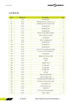
Page 56: ...joint 2 11 N C Sealing joint 1 12 N C Sealing joint 1 13 N C Sealing joint 2 14 N C Control valve ceramic plate 1 15 N C Control valve obturator 1 16 N C O ring seal 1 17 N C Basket ball lower part 4...

Page 57: ...over plate 1 39 N C Valve cover 1 40 N C Guide bushing 2 41 N C Piston rod 1 42 N C Valve sealing joint 2 43 N C Sealing cover 2 44 N C Countersunk screw 4 45 N C Hexagon screw 18 46 N C Cylinder head...

Page 58: ...Kit 01D140E Pump Ind Reference Description Qty 144907016 EPDM Diaphragm Kit 01D140E 1 1 N C Diaphragms 2 Recommended spare parts N C Not Commercially Available Ball valve Kit 01D140 01D140E Pumps Ind...

Page 59: ...ic valve Kit 01D140 01D140E Pumps Ind Reference Description Qty 144907014 Pneumatic valve Kit 1 2 N C Sealing joint for valve cover 1 3 N C Sealing joint for main valve 1 4 N C Sealing joint 2 5 N C S...

Page 60: ...Pneumatic valve sealing joints Kit 1 2 N C Sealing joint for valve cover 1 3 N C Sealing joint for main valve 1 4 N C Sealing joint 2 5 N C Sealing joint 1 6 N C Sealing joint 1 9 N C O ring seal 4 1...

Page 61: ...been applied EN ISO 12100 2010 Safety of machinery General principles for design Risk assesment and risk reduction EN 809 1998 A1 2009 Pumps and pump units for fluids general safety requirements EN I...

Reviews: