SAMES KREMLIN
- 6 -
N° : 578.022.120-UK-2110
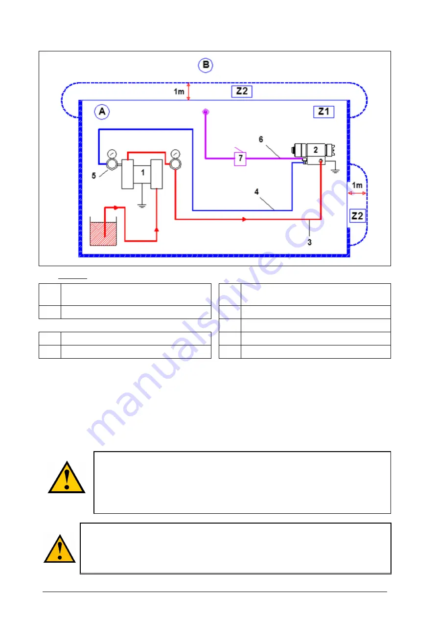
INSTALLATION DIAGRAM
Captions
A
Explosive area area 1 (Z1) or area 2 (Z2) :
spray booth
3 Fluid
hose
B
Non explosive area
4
Conductive
air hose (spraying air)
5 Air
regulator
1
Pump
6
Air hose (control air)
2
Pneumatic automatic gun
7
3 way-valve or electrovalve
1 - By means of a fluid hose (3), connect the gun fluid fitting to the pump. Tighten firmly the fittings.
2 - By means of a
conductive
air hose (4), connect the gun 'Spraying air' fitting (2) to an air
regulator (5) that can supply at least 3 bar / 43.5 psi (
spraying air).
3 - By means of an air hose (6), connect the gun 'Control air' fitting to the valve or the electrovalve
(7) that will control the opening and the closing of the gun.
A minimum pressure of 3 or 4 bar / 43.5 or 8 psi is necessary to control the gun
(
control air).
Nota : The gun (and its eventual base)
must be
grounded by,
at least,
one of the two
next solutions :
by means of the fixing device on the machine,
by means of the conductive or static conductive fluid hose.
The ground resistance between the gun and the floor must be
≤
1 M
Ω
.
The 1 m / 39.37" distance indicated in these diagrams is given for information
purposes only and hold harmless to SAMES KREMLIN. The user is responsible for
the extraction and conditioning of the painting area where the equipment is used, for
working conditions conditions (refer to EN 60079-10 standard). The 1 m / 39.37"
distance may be modified if trials carried out by the user deem this necessary.


