


10
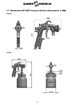
5.3
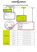
Nozzle characterization principle
Nozzle parameter
Technology
Nozzle size
H: HVLP
C: CONVENTIONAL
•
12 : 1.2 mm
•
15 : 1.5 mm
•
18 : 1.8 mm
6
Installation
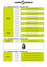
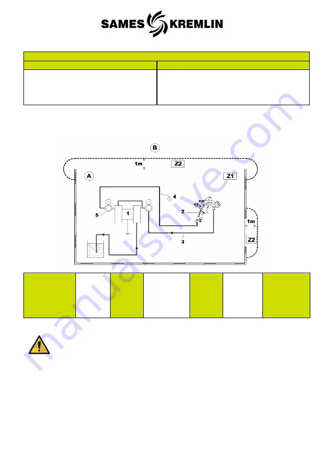
6.1
General Installation Diagram
A- Explosive
area
Area 1 (Z1)
or area 2
(Z2) : spraybooth
B – non
explosive
area
1 - Pump
2 –Airspray
gun
3 – Fluid
product
4 -
Antistatic
air hose
5 – Air
regulator
The 1 m / 39.37" distance indicated in the diagram is given for information
purposes only and hold harmless to SAMES KREMLIN. The user is responsible for the
extraction and conditioning of the painting area where the equipment is used, for working
conditions.


