background image


2 BALL PUMP 

588 cm3 

Pump REXSON 2B588 


User Manual 528135110 

2021-09-15 

Index C 

Translation of the original instructions 


SAMES KREMLIN SAS 

13 Chemin de Malacher 


38240 Meylan 


www.sames-kremlin.com


33 (0)4 76 41 60 60 


Summary of Contents for REXSON 2B588

Page 1: ... PUMP 588 cm3 Pump REXSON 2B588 User Manual 528135110 2021 09 15 Index C Translation of the original instructions SAMES KREMLIN SAS 13 Chemin de Malacher 38240 Meylan www sames kremlin com 33 0 4 76 41 60 60 ...

Page 2: ...ny form whatsoever and any exploitation or communication of its contents are prohibited except with the express written consent of SAMES KREMLIN The descriptions and features contained in this document are subject to change without notice SAMES KREMLIN 2021 ...

Page 3: ...S NUMBER OF HIGH VISCOSITY PUMPS 17 4 2 TABLE 1 FLUID SECTION AIR MOTOR SELECTION 18 4 3 TABLE 2 FLUID SECTION PUMP FOOT MATERIAL SELECTION 18 4 4 TABLE 3 SEALS PACK SELECTION 19 5 IDENTIFICATION 20 5 1 DESCRIPTION OF THE MARKING OF THE PLATE 20 5 2 CORRESPONDENCE TABLE NEW PART NUMBERS SIGNIFICANT DESIGNATIONS 22 5 3 CORRESPONDENCE TABLE EXISTANT PART NUMBERS SIGNIFICANT DESIGNATIONS 23 6 TECHNIC...

Page 4: ...ts Remedies to apply 35 10 MAINTENANCE 37 10 1 PREVENTIVE MAINTENANCE PLAN 38 Fluid section 38 10 2 GENERAL PRECONISATION MAINTENANCE 39 11 DISASSEMBLY REASSEMBLY OPERATION 40 Greases and thread lockers designations 40 Disassembly of the Pump 42 Lower Valve 42 Wet Cup seals 43 Upper Valve and Piston Rod seals 44 Reassembly of the fluid section 44 12 SPARE PARTS 45 Lower adapter flange 48 Recommend...

Page 5: ... equipment and we thank you for it We have taken the utmost care from design to manufacture so that this equipment gives you complete satisfaction For a good use and an optimal availability we invite you to read this manual carefully before using your equipment Additional Documentations Documentation Reference Air Motor 6000 582147110 Air Motor 7000 582148110 Air Motor 9000 582149110 IMPORTANT Bef...

Page 6: ...ciate The warranty excludes wear parts deterioration or wear resulting from abnormal or unscheduled use by SAMES KREMLIN failure to observe instructions for proper operation or lack of maintenance The warranty is limited to the repair or exchange of parts returned to our factory and recognized as defective by us and does not cover the listed wear parts Any costs resulting from the operation cannot...

Page 7: ...Declaration of Conformity 7 1 Declaration of Conformity Refer to the existing declaration delivered with the product ...

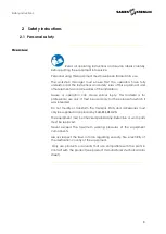
Page 8: ... cause serious injury This material is for professional use only It must be used only for the purpose for which it was intended Do not modify or transform the material Parts and accessories must only be supplied or approved by SAMES KREMLIN The equipment must be checked periodically Defective or worn parts must be replaced Never exceed the maximum working pressures of the equipment components Alwa...

Page 9: ...ion Danger hot parts or surfaces Danger flammability risks Danger electricity Risk of explosion Danger user Warning Danger Gloves required Grounding Protective helmet Hearing pro tection Mandatory respiratory protection Safety shoes Protective clothing Protective visor Safety glasses is mandatory Refer to the manual instruction leaflet ...

Page 10: ...t components Danger of Pressure Safety requires that a pressure relieve shutoff valve be mounted on the pump motor supply circuit to allow trapped air to escape when the supply is shut off Without this precaution the residual air from the engine may cause the motor pump to operate and cause a serious accident Similarly a material bleed valve must be installed on the material circuit so that materi...

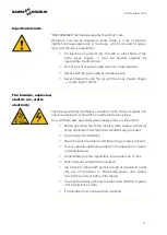
Page 11: ...ng insufficient ventilation open flames or sparks can cause an explosion or fire which could result in serious injury To avoid these risks especially when using pumps it is imperative Before operating the Pump supply system make sure that all Pump equipment and material containers are grounded To ensure good ventilation Keep the work area clean and free of rags papers solvents Do not operate elect...

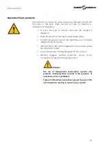
Page 12: ...in the application in a container designed for that purpose Treat product waste with the legislation of the country where the equipment is used To wear protective clothing designed for that purpose Wearing goggles hearing protectors gloves shoes coveralls and masks for the respiratory tract Attention The use of halogenated hydrocarbon solvents and products containing these solvents in the presence...

Page 13: ...ir motor is intended to be coupled to a pump Never modify the coupling system Keep hands away from moving parts The moving parts must be kept clean Before commissioning or using the motor pump read carefully the DECOMPRESSURIZATION PROCEDURE Check the proper operation of the pressure relief and bleed air valves Tubing Recommendations Keep hoses away from traffic areas moving parts and hot areas Ne...

Page 14: ...herent risks to staff and the environment Wear and tear maladjustment malfunction of equipment or machines and the quality of the finished product The user will have to identify and prevent the potential dangers inherent to the implemented products such as Toxic vapors Fire Explosions It will determine the risks of immediate reactions or due to repeated exposures to the staff SAMES KREMLIN decline...

Page 15: ...l be earthed via the earth cable of this motor This earth cable must be connected to a safe earth ground Have the earth ground continuity checked by a qualified electrician If the ground continuity is not assured check terminal wire and grounding point Never operate the equipment without solving this problem Do not store more flammable products than necessary inside the work area These products mu...

Page 16: ... designed and manufactured with high quality materials and components that can be recycled and reused European Directive 2012 19 EU applies to all devices marked with this logo crossed out bin Find out about the collection systems available for electrical and electronic devices Comply with the rules in your area and do not dispose of old appliances with household waste Proper disposal of this old ...

Page 17: ...Significant designation Ex 1 cP 1 mPa s 2B R E X 0588 Technology Ball pump 2B Air Motor None XX Motor 6000 60 Motor 7000 70 Motor 9000 90 Refer table 1 Material of construction CS Mixed materials SS Stainless steel SC Stainless steel Carbide valves Refer table 2 Pump foot WM Wall Mounted FP Follower plate Refer table 2 Seal pack PTFE 01 PTFE FEP 02 PE 03 Leather 04 PTFEG 05 PU 06 Reserved for spec...

Page 18: ...ce bar psi bar psi XX NONE 60 MOTOR 6000 10 1 6 100 60 900 582147110 70 MOTOR 7000 18 1 6 100 110 1600 582148110 90 MOTOR 9000 30 1 6 100 180 2600 582149110 4 3 Table 2 Fluid Section Pump Foot Material Selection Available foot pump Available material CS SS SC Mixed materials Stainless steel Mixed Materials Carbide valve WM Wall mounted X FP Follower plate 2B R E X 0588 2B R E X 0588 ...

Page 19: ...PTFE and PE 04 Leather FKM Leather and PE Leather and PE 05 PTFEG FKM PTFEG PTFEG 06 PU FKM PU and PE PTFEG 07 PTFEV FKM PU and PE PE and PTFEV PTFE Polytetrafluorothylene Teflon like properties PTFEG PTFE Graphite impregnated PE Polyethene UHMWPE FKM Flouroelastomer Viton like properties PU Polyurethane PTFEV PTFE Glass impregnated FEP Encapsulated O Ring Teflon like properties over Viton or Sili...

Page 20: ... Voltage Directive 2006 95 EEC EMV Directive 2004 108 EEC Safety of machinery Basic terms general implementation guidelines DIN EN ISO 12100 T1 T2 Safety of machinery Temperatures of touchable surfaces EN 563 Safety of machinery Safety engineering requirements for fluid power systems and their components Pneumatics EN 983 ATEX Directive 2014 34 EU II 2 G Group II Category 2 Gas ...

Page 21: ...t pressure Bar Psi AIR Maximum air pressure Bar Psi RAPPORT RATIO Pump pressure ratio CE EC European conformity II2G Use in explosive area II group II 2 category 2 Surface material intended for an environment in which explosive atmospheres due to gases vapors mists are likely to occasionally occur during normal operation G gas IIA T3 IIA Reference gas for equipment qualification T3 Maximum surface...

Page 22: ... Motor MO 44 MOT6000 60 45 MOT7000 70 46 MOT9000 90 M Material MA 1 Mixed Steels CS 2 Stainless Steel SS 4 Stainless Steel Carbide valve SC S Seal SE 1 PTFE 01 2 PTFE FEP 02 3 PE 03 4 Leather 04 5 PTFEG 05 6 PU 06 7 PTFEV 07 F Foot FO 1 Wall mounted WM 2 Follower plate Ø 105 mm FP Documentation Reference Air Motor 6000 582147110 Air Motor 7000 582148110 Air Motor 9000 582149110 ...

Page 23: ...ant designation Motor Material Foot Seal 461 251 760 101 REX2B0588 60 CS WM 01 MOT6000 10 1 CS Mixed Steels WM Wall mounted 01 PTFE 461 251 760 102 REX2B0588 60 CS WM 02 MOT6000 10 1 CS Mixed Steels WM Wall mounted 02 PTFE FEP 461 251 760 104 REX2B0588 60 CS WM 04 MOT6000 10 1 CS Mixed Steels WM Wall mounted 04 Leather ...

Page 24: ...ion and seals kit Packings Depending on seal kit Available Motors Motor selection XX 60 70 90 NONE MOTOR 6000 MOTOR 7000 MOTOR 9000 Pressure Ratio 10 1 18 1 30 1 Maximum Air Inlet Pressure bar 6 6 6 psi 100 100 100 Maximum Outlet Fluid Pressure bar 60 110 180 psi 900 1600 2600 Minimum Outlet Fluid Pressure bar 15 27 45 psi 218 392 653 Complete Pump Weight Kg 57 64 73 Lbs 125 7 141 1 161 Air consum...

Page 25: ...eel Stainless steel Stainless steel Cylinder Carbon steel Chromium Treatment Stainless steel Chromium Treatment Carbon steel Chromium Treatment Piston Upper check Piston rod Stainless steel Chromium Treatment Stainless steel Chromium Treatment Stainless steel Chromium Treatment Valve body Carbon steel Stainless steel Stainless steel Valve ball Carbon steel Stainless steel Carbide Valve seat Carbon...

Page 26: ... flap 2 closes and the lower flap 3 opens The piston 1 expels the product from the upper chamber V2 to the outside and sucks the product to fill the lower chamber V1 When the piston 1 is lowered the upper flap 2 opens and the lower flap 3 closes The piston 1 compresses the fluid in the lower chamber V1 and transfers it to the upper chamber V2 Since the volume of the upper chamber V2 is half that o...

Page 27: ...ement of the product inside the pump and its accessories as well as that caused by the seals creates static electricity that can cause fire or explosion Therefore the fluid section system must be earthed via the motor ground cable see the motor instruction manual for its ground connection ...

Page 28: ...hat the order in which the cables hoses and pipes are connected is in accordance with the connection diagram Make sure that all cable connectors hose and pipe connections are correctly fitted Remember that unconnected or incorrectly connected cables hoses and pipes can lead to malfunctions that endanger the safety of operating personnel 7 2 1 Fluid supply connection If the supply pressure is highe...

Page 29: ...sure drops 7 3 Storage Pump Place the equipment away from moisture after closing the various air inlets and various openings plugs Storage before installation Storage ambient temperature 0 50 C Protect the unit against dust water runoff moisture and shocks Storage after installation Protect the unit against dust water runoff moisture and shocks ...

Page 30: ... removed by flushing with a suitable solvent At the end of the day flush with a suitable solvent It is advisable to stop the fluid section in the low position in order to prevent the product from taking hold of the piston rod Motor The Air motors are tested before their shipment Nevertheless Before coupling the Air motor to a fluid section pump it is recommended to run the air motor at a low air p...

Page 31: ...tening Tightening of the Wet Cup Verify cup is filled with lubricant T Run the pump then tighten the cup after 10 minutes again after 1 hour then after1 day of operation In the event of a leak the cup must be tightened Tightening procedure Depressurize the Air motor see depressurization procedure Depressure the product circuit see depressurization procedure Tighten the cup clean it and fill it wit...

Page 32: ...on valve ball cage screw Depending upon the fluid viscosity to be pumped adjust the height of the screw 19C to increase the ball up motion Lock the screw on the lock nut 19B For a full description of spare parts see Part 12 Spare Parts 19B 19A 19C ...

Page 33: ...sulting from the destruction the occultation or the total or partial removal of the protectors 9 3 Start up Pumps are tested for operation at the factory using a light weight oil lubricant Before commissioning this lubricant must be removed by flushing with a suitable solvent At the end of the day flush with a suitable solvent It is advisable to stop the fluid section in the low position in order ...

Page 34: ... off valve to remove residual air from the motor Unlock the gun valve tap Bring the gun valve tap close to a metal bucket in order to recover the product Hold it against the wall of the bucket to avoid interrupting the grounding continuity if necessary use the wire with clamp to ground the metal bucket Open the gun valve tap in order to drain the circuit Lock the gun valve tap in the OFF position ...

Page 35: ...s stopped The fluid is polymerized hardened dried in the pump Clean the pump change the parts if necessary The cup is too tightened Loosen Broken part s in the pump Remove check replace The motor seems to operate but the pump does not deliver product Internal parts of the motor failing Check the operating of the motor Defective coupling Check coupling The pump operates but irregular flow Valve clo...

Page 36: ...ls incorrectly mounted or damaged Check the mounting change if necessary The pump does not deliver enough pressure Insufficient air pressure to the motor valve insufficiently open air leak Check adjust Insufficient air inlet on the motor or outlet clogged hose not adapted Check filter mounting hose not adapted Cup or head piston seals too tightened Check mounting or loosen cup nut Abnormal operati...

Page 37: ...r only the most common problems If the information given here does not solve the problem you are experiencing please contact your local SAMES KREMLIN representative for assistance During prolonged shutdown stop the pump when the piston is in the low position Guards motor cover coupling guard housings are set up for safe use of the equipment The manufacturer can not be held responsible in case of b...

Page 38: ... Check the condition of the hoses Observe the piston rod of the pump Do not let the product dry onto the piston rod Check the lubricant level inside the cup keep it at half level Fill it if necessary It is normal for this lubricant to stain Tighten the packing cup moderately with the supplied wrench if necessary Check the tightness of the components If the pump is equipped with a pusher plate chec...

Page 39: ...ed it is imperative to follow the depressurization procedure and the safety instructions Before each reassembly Clean the parts with the appropriate cleaning solvent Fit new seals if necessary after greasing them Grease the piston and the inside of the cylinder to avoid damaging the seals Fit new parts if necessary ...

Page 40: ...fore each reassembly Clean the parts with appropriate cleaning solvent Fit new seals if necessary after greasing them Grease the piston and the inside of the cylinder to avoid damaging the seals see table below Fit new parts if necessary Greases and thread lockers designations Index Instruction Description Part number A 1 PTFE grease TECHNI LUB grease 10 ml 0 0026 US gal 560 440 101 A 2 Anti seize...

Page 41: ...sembly Operation 41 Fluid Section Follower plate Wall Mounted all versions REX2B0588 FP REX2B0588 WM For a full description of spare parts see Part 12 Spare Parts A 2 A 1 A 1 A 1 A 2 A 1 A 1 A 1 C 1 A 1 A 1 A 1 C 1 S 1 ...

Page 42: ...mbly 26 for the fluid section model REX2B0588 FP the flange 31 and the O Ring 29 Take off the piston 15 downwards Put aside the cylinder 10 Lower Valve Unscrew the body of the filling body 26 Take off the valve stop 19 and the ball 22 Take off the seat 23 Take off the seal 24 Take off the first seal 9 Clean the parts check them if they are damaged or worn change them Reinstall the parts in the rev...

Page 43: ...rewing the extractors in the 3 M8 holes of the cartridge Take off the F washers 6 and the seals 11 Take off the first M washer 12 Take off the seasl 11 Unscrew the housing of the wet cup nut 7b check and change if necessary the O Ring 7c Clean the parts check them if they are damaged or worn change them Reinstall the parts in the reverse order of the disassembly sequence ...

Page 44: ...m if there are damaged or worn change them Reinstall the parts in the reverse order of the disassembly sequence Reassembly of the fluid section Lubricate the cup seals and piston rod seals Slide the piston rod assembly 15 inside the body 7 push it upwards Screw the cylinder 10 into the body 7 Reinstall the protection 4 the connection flange 1 and the tie rods 14 Screw the nuts 16 Couple the fluid ...

Page 45: ...IN accessories and spare parts designed to withstand the pump s operating pressures Fluid Section Follower plate Wall Mounted all versions REX2B0588 FP REX2B0588 WM WARNING these parts are not supplied with the fluid section alone as they depend on the engine ...

Page 46: ...7D Screw 930 151 279 12 3 8 Plug 906 333 102 552 337 906 333 102 1 3 9 O Ring According to seals pack 1 10 Cylinder 210 706 210 893 210 706 1 2 12 M washer 210 731 1 1 13 Pin See motor coupling kit table 2 3 14 Tie rod See motor coupling kit table 4 3 15 Piston rod 210 704 210 892 210 704 1 2 16 Lock nut 88 339 4 3 17 Ball 86 032 87 332 87 532 1 2 18 Seat 210 705 210 734 210 705 1 2 19 Ball guide ...

Page 47: ...6 045 87 344 87 544 1 2 23 Seat 210 708 210 896 211 470 1 2 26 Suction valve body 210 707 210 714 210 897 210 714 1 2 25 O Ring 84 470 84 470 1 1 28 Follower plate adaptation 210 674 210 674 1 3 29 O Ring 84 457 84 457 1 1 31 Flange 2 parts 210 686 210 686 1 3 40 Cup wrench 044 950 008 1 3 Recommended maintenance parts N S Denotes parts are not serviceable Level 1 Preventive maintenance Level 2 Co...

Page 48: ...nance Level 3 Exceptional maintenance Recommended Seals pack Code Composition Use 01 PTFE FKM Solvent Ether Ketone Aromatic alcohol some varnishes and paints 02 PTFE FKM FEP Solvent Ether Ketone Aromatic alcohol some varnishes and paints PU paints Pharmacy Cosmetics Some foodstuffs 03 PTFE PE FKM Epoxy glue Butyl Silicone Some varnishes Paint 04 PE LEATHER FKM Paint Varnishes Grease Oil Ink Hydro ...

Page 49: ... PTFE 1 84 458 PTFE Piston packing 6 210 725 PTFE 6 210 725 PTFE 3 3 210 726 210 725 PE PTFE Adjustment block 4 210 729 ST STEEL 4 210 729 ST STEEL 4 210 729 ST STEEL 7C Cartridge seal 1 909 420 265 FKM 1 909 420 265 FKM 1 909 420 265 FKM PE PE PE PE PE PTFE PE PE PE PE PE PTFE PE PE PE PE PE PTFE PE PE PE PE PE PTFE PE PE PE PTFE PTFE PE PTFE PTFE PTFE PTFE PTFE PE PTFE PTFE PTFE PTFE PTFE PE PTF...

Page 50: ...packing 3 2 210 726 210 728 PE LEATHER 6 210 727 PTFE G 6 210 727 PTFE G Adjustment block 4 210 729 ST STEEL 4 210 729 ST STEEL 4 210 729 ST STEEL 7C Cartridge seal 1 909 420 265 FKM 1 909 420 265 FKM 1 909 420 265 FKM PE PTFE G RING LEATHER PTFE G PU PE PTFE G PU LEATHER PTFE G PU PE PTFE G PU LEATHER PTFE G PU PE PTFE G PE PTFE G PTFE G PE PTFE G PE LEATHER PTFE G PTFE PE PTFE G PE LEATHER PTFE ...

Page 51: ...4 456 FKM Cup packing 1 5 210 722 84 395 PE PU 25 O Ring 1 84 458 PTFE Piston packing 3 3 210 726 211 318 PE PTFE V Adjustment block 4 210 729 ST STEEL 7C Cartridge seal 1 909 420 265 FKM PU PU PU PU PU PE PE PTFE V PE PTFE V PE PTFE V 11 45 30 11 45 Quantity to be assembled as required According to pump ...

Reviews: