background image


2 BALL PUMP 

750 cm3 

Pump REXSON 2B750 


User Manual 582171110 

2021-03-02 

Index A 

Translation of the original instructions 


SAMES KREMLIN SAS 

13 Chemin de Malacher 


38240 Meylan 


www.sames-kremlin.com


33 (0)4 76 41 60 60 


Summary of Contents for REXSON 2B750

Page 1: ...PUMP 750 cm3 Pump REXSON 2B750 User Manual 582171110 2021 03 02 Index A Translation of the original instructions SAMES KREMLIN SAS 13 Chemin de Malacher 38240 Meylan www sames kremlin com 33 0 4 76 41...

Page 2: ...y form whatsoever and any exploitation or communication of its contents are prohibited except with the express written consent of SAMES KREMLIN The descriptions and features contained in this document...

Page 3: ...XSON PARTS NUMBER OF HIGH VISCOSITY PUMPS 17 4 2 TABLE 1 FLUID SECTION AIR MOTOR SELECTION 18 4 3 TABLE 2 FLUID SECTION PUMP FOOT MATERIAL SELECTION 18 4 4 TABLE 3 SEALS PACK SELECTION 18 5 IDENTIFICA...

Page 4: ...Remedies to apply 34 10 MAINTENANCE 36 10 1 PREVENTIVE MAINTENANCE PLAN 37 Fluid section 37 10 2 CURATIVE MAINTENANCE 38 11 DISASSEMBLY REASSEMBLY OPERATION 39 Greases and thread lockers designations...

Page 5: ...most care from design to manufacture so that this equipment gives you complete satisfaction For a good use and an optimal availability we invite you to read this manual carefully before using your equ...

Page 6: ...iate The warranty excludes wear parts deterioration or wear resulting from abnormal or unscheduled use by SAMES KREMLIN failure to observe instructions for proper operation or lack of maintenance The...

Page 7: ...Declaration of Conformity 7 1 Declaration of Conformity Refer to the existing declaration delivered with the product...

Page 8: ...cause serious injury This material is for professional use only It must be used only for the purpose for which it was intended Do not modify or transform the material Parts and accessories must only b...

Page 9: ...ion Danger hot parts or surfaces Danger flammability risks Danger electricity Risk of explosion Danger user Warning Danger Gloves required Grounding Protective helmet Hearing protection Mandatory resp...

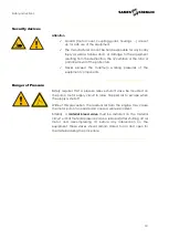
Page 10: ...components Danger of Pressure Safety requires that a pressure relieve shutoff valve be mounted on the pump motor supply circuit to allow trapped air to escape when the supply is shut off Without this...

Page 11: ...g insufficient ventilation open flames or sparks can cause an explosion or fire which could result in serious injury To avoid these risks especially when using pumps it is imperative Before operating...

Page 12: ...n the application in a container designed for that purpose Treat product waste with the legislation of the country where the equipment is used To wear protective clothing designed for that purpose Wea...

Page 13: ...r motor is intended to be coupled to a pump Never modify the coupling system Keep hands away from moving parts The moving parts must be kept clean Before commissioning or using the motor pump read car...

Page 14: ...erent risks to staff and the environment Wear and tear maladjustment malfunction of equipment or machines and the quality of the finished product The user will have to identify and prevent the potenti...

Page 15: ...s will be earthed via the earth cable of this motor This earth cable must be connected to a safe earth Have the earth continuity checked by a qualified electrician If earth continuity is not assured c...

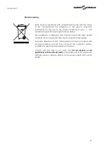
Page 16: ...esigned and manufactured with high quality materials and components that can be recycled and reused European Directive 2012 19 EU applies to all devices marked with this logo crossed out bin Find out...

Page 17: ...000 cP Different configurations are available Significant designation Ex 1 cP 1 mPa s 2B R E X 0750 Technology Ball pump 2B Air Motor None XX Motor 7200 72 Motor 9200 92 Refer table 1 Material of cons...

Page 18: ...lable pump foot Available material CS Mixed materials WM Wall mounted FP Follower plate 4 4 Table 3 Seals Pack Selection Available Seals Packing Static seals O rings Upper seals packing Piston seals p...

Page 19: ...Voltage Directive 2006 95 EEC EMV Directive 2004 108 EEC Safety of machinery Basic terms general implementation guidelines DIN EN ISO 12100 T1 T2 Safety of machinery Temperatures of touchable surfaces...

Page 20: ...pressure Bar Psi AIR Maximum air pressure Bar Psi RAPPORT RATIO Pump pressure ratio CE EC European conformity II2G Use in explosive area II group II 2 category 2 Surface material intended for an envi...

Page 21: ...nificant Designation 61 MO 0750 M S F 000 REX2B0750 MO MA FO SE Options MO Motor MO 55 MOT7200 72 56 MOT9200 92 M Material MA 1 Mixed Steels CS S Seal SE 5 PTFE G 05 6 PU 06 F Foot FO 1 Wall mounted W...

Page 22: ...number Significant designation Motor Material Foot Seal 105 214 REX2B0750 XX CS WM 06 None CS Mixed Steels WM Wall mounted 06 PU 49 225 214 REX2B0750 92 CS WM 06 MOT9200 40 1 CS Mixed Steels WM Wall...

Page 23: ...nstruction and seals pack Packings Depending on seal pack Available Motors Motor selection XX 72 92 NONE MOTOR 7200 MOTOR 9200 Pressure Ratio 25 1 40 1 Maximum Air Inlet Pressure bar 6 6 psi 100 100 M...

Page 24: ...ruction CS Mixed materials Pump body Wet Cup Carbon steel Upper body Carbon steel Cylinder Carbon steel Chromium treatment Piston Upper check Piston rod Stainless steel chromed Valve body Carbon steel...

Page 25: ...closes and the lower flap 3 opens The piston 1 expels the product from the upper chamber V2 to the outside and sucks the product to fill the lower chamber V1 When the piston 1 is lowered the upper fla...

Page 26: ...the product inside the pump and its accessories as well as that caused by the seals creates static electricity that can cause fire or explosion Therefore the fluid section system must be earthed via t...

Page 27: ...order in which the cables hoses and pipes are connected is in accordance with the connection diagram Make sure that all cable connectors hose and pipe connections are correctly fitted Remember that un...

Page 28: ...ure drops 7 3 Storage Pump Place the equipment away from moisture after closing the various air inlets and various openings plugs Storage before installation Storage ambient temperature 0 50 C Protect...

Page 29: ...removed by flushing with a suitable solvent At the end of the day flush with a suitable solvent It is advisable to stop the fluid section in the low position in order to prevent the product from takin...

Page 30: ...ening Tightening of the Wet Cup Verify cup is filled with lubricant T Run the pump then tighten the cup after 10 minutes again after 1 hour then after1 day of operation In the event of a leak the cup...

Page 31: ...pump is mainly dedicated to the transfer and application of viscous products the pin is when leaving the factory positioned at the highest point This allows the ball to move far away from the seat and...

Page 32: ...ulting from the destruction the occultation or the total or partial removal of the protectors 9 3 Start up Pumps are tested for operation at the factory using a light weight oil lubricant Before commi...

Page 33: ...off valve to remove residual air from the motor Unlock the gun valve tap Bring the gun valve tap close to a metal bucket in order to recover the product Hold it against the wall of the bucket to avoid...

Page 34: ...stopped The fluid is polymerized hardened dried in the pump Clean the pump change the parts if necessary The cup is too tightened Loosen Broken part s in the pump Remove check replace The motor seems...

Page 35: ...s incorrectly mounted or damaged Check the mounting change if necessary The pump does not deliver enough pressure Insufficient air pressure to the motor valve insufficiently open air leak Check adjust...

Page 36: ...mmon problems If the information given here does not solve the problem you are experiencing please contact your local SAMES KREMLIN representative for assistance During prolonged shutdown stop the pum...

Page 37: ...ion of the hoses Observe the piston rod of the pump Do not let the product dry onto the piston rod Check the lubricant level inside the cup keep it at half level Fill it if necessary It is normal for...

Page 38: ...o follow the decompression procedure and the safety instructions Before each reassembly Clean the parts with the appropriate cleaning solvent Fit new seals if necessary after greasing them Grease the...

Page 39: ...ly Clean the parts with appropriate cleaning solvent Fit new seals if necessary after greasing them Grease the piston and the inside of the cylinder to avoid damaging the seals see table below Fit new...

Page 40: ...embly Operation 40 Fluid Section Follower plate Wall Mounted with seals pack 05 REX2B0750 FP 05 REX2B0750 WM 05 For a full description of spare parts see Part 12 Spare Parts A 2 A 1 A 1 A 1 A 2 A 1 A...

Page 41: ...embly Operation 41 Fluid Section Follower plate Wall Mounted with seals pack 06 REX2B0750 FP 06 REX2B0750 WM 06 For a full description of spare parts see Part 12 Spare Parts A 2 A 1 A 1 A 1 A 2 A 1 A...

Page 42: ...ody with a vice 7 Unscrew the foot valve body assembly 26 Take off the piston 15 downwards Put aside the cylinder 10 Lower valve Unscrew the body of the foot valve body 26 Take off the ball cage 19 an...

Page 43: ...ond M washer 20 Clean all the parts check them if there are damaged or worn change them Clean and reinstall the parts in the reverse order of the disassembly sequence Wet Cup seals REX2B0750 06 Unscre...

Page 44: ...and change it Clean all the parts check them if there are damaged or worn change them Reinstall the parts in the reverse order of the disassembly sequence When reassembling assemble by means of Locti...

Page 45: ...ssories and spare parts designed to withstand the pump s operating pressures Fluid Section Follower plate Wall Mounted with seals pack 05 REX2B0750 FP 05 REX2B0750 WM 05 WARNING these parts are not su...

Page 46: ...pare parts 46 Fluid Section Follower plate Wall Mounted with seals pack 06 REX2B0750 FP 06 REX2B0750 WM 06 WARNING these parts are not supplied with the fluid section alone as they depend on the engin...

Page 47: ...it 1 1 13 Pin See motor coupling kit table 2 3 14 Tie rod See motor coupling kit table 4 3 15 Piston rod 211 787 1 2 16 Lock nut 88 338 4 3 17 Ball 86 032 1 2 18 Piston bush 203 176 1 2 19 Valve stop...

Page 48: ...N S 209 582 2 4 Protective housing N S 208 236 1 14 Tie rod N S 203 169 4 Recommended maintenance parts N S Denotes parts are not serviceable Level 1 Preventive maintenance Level 2 Corrective maintena...

Page 49: ...84 485 FKM Cup packing 8 203 162 PTFE G 12 O Ring 1 84 483 FKM Piston packing 8 203 162 PTFE G 28 O Ring 1 84 484 FKM PTFE G Spacer Ind 6 PTFE G PTFE G PTFE G PTFE G PTFE G PTFE G PTFE G PTFE G PTFE G...

Page 50: ...C 9 O Ring 2 909 420 249 FKM Cup packing 8 84 334 PU Piston packing 8 203 162 PTFE G 27 Ring 1 203 163 PA 28 O Ring 1 80 040 FKM 7a O Ring 1 80 039 FKM Ring Ind 6 PU PU PU PU PTFE G PTFE G PTFE G PTFE...

Reviews: