Revised A
56
6301
6. Assembly and disassembly (continued)
6.4 Turbine motor, injector, restrictor (continued)
6.4.1 Disassembly (continued)
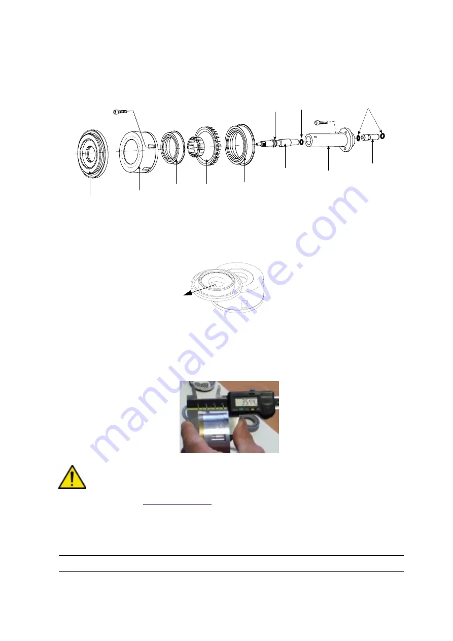
• Step 2: Remove the deflector (6) with its seal by sliding it with your thumbs .
• Step 3: Remove the drive wheel (5) using the tool (P/N. 1308679) .
• Step 4: Remove the rotor (1) by sliding it straight across the stator (3).
• Step 5: Remove the magnet (4).
• Step 6: Measure with a calliper the stator assy thickness. The reading should be between 35 mm
mini and 35.45 mm maxi.
CAUTION : Below 35 mm, the stator assy has to be replaced. Between 35 mm and 35.45 mm, the
stator can be repaired (
1
2
3
4
5
6
7
8
9
10
11
2
12
DES01504
DES01506


