background image

Pag. 18/21 

axial piston

R

axial piston

axial piston

R

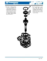
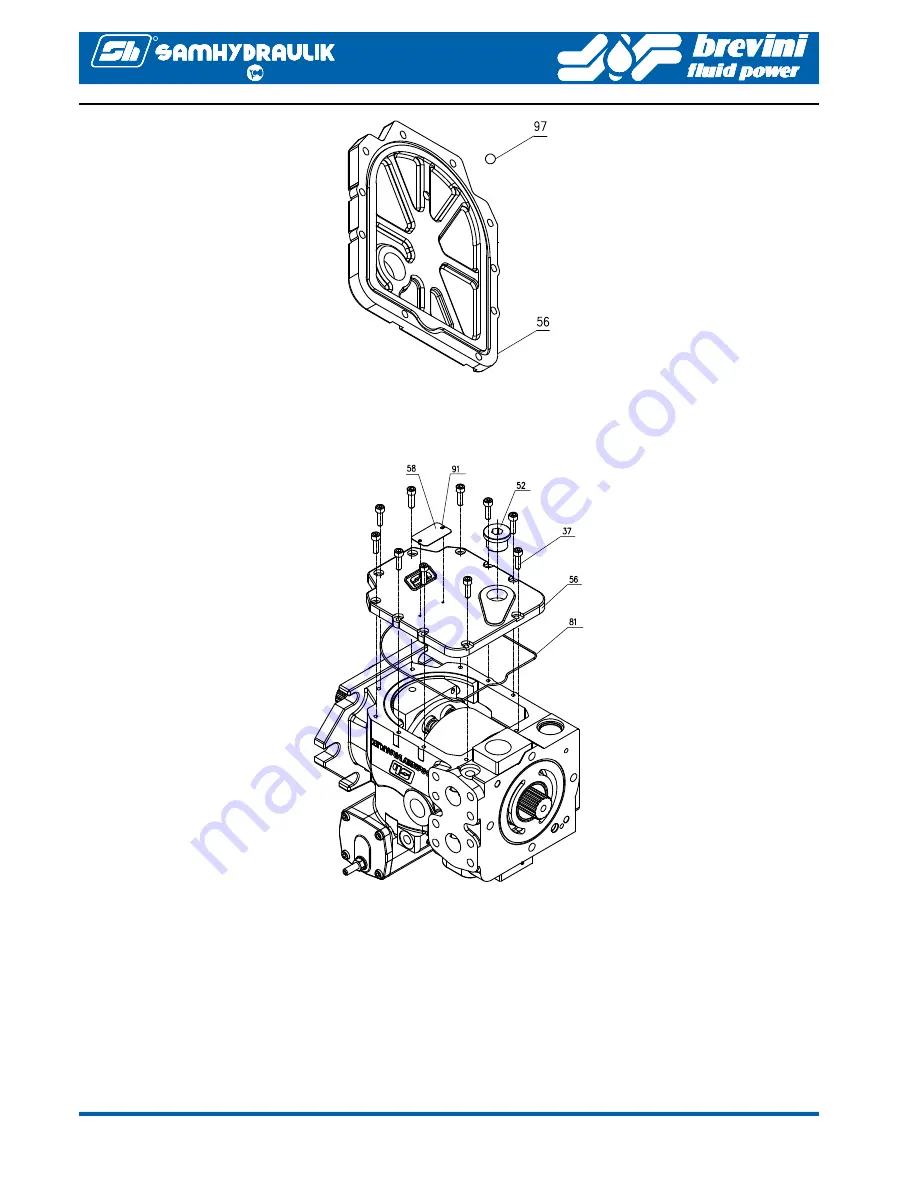
14. Mount ball (97) into its seat of 

lower cover (56). 

14. Montare la sfera (97) nell’apposita 

sede sul coperchio di chiusura in-
feriore (56). 

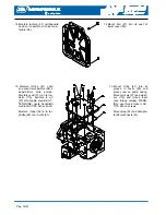
15.  

Montare l’Oring (81) nella 

sua cava del coperchio (56) e 
quest’ultimo sulla pompa. 
Montare le viti (37) con le ron-
delle (113). Avvitare le viti 
(37) alla coppia prevista. AT-
TENZIONE: usare frenafiletti 
medio LOCTITE 243 sulle viti. 

Montare i tappi (52) e la tar-
ghetta (58) con i rivetti (91). 

15.  

Mount Oring (81) into its 

groove in cover (56) and 
place cover on pump casing. 
Mount screws (37) and wash-
ers (113) and torque them 
(see torque values). WARN-
ING: use thread locker LOC-
TITE 243 on screws. 

Mount plug (52) and data pla-
te (58) with rivets (91). 

Summary of Contents for SH6V 75

Page 1: ...CORPO POMPA SH6V 75 PUMP ASSEMBLY MANUALE DI USO E MANUTENZIONE SERVICE MANUAL Cod 06 0006 A02...

Page 2: ...Pag 2 21 axial piston R axial piston axial piston R SEZIONATO POMPA SH6V 75 PUMP CUTAWAY VIEW...

Page 3: ...Pag 3 21 axial piston R axial piston axial piston R SEZIONATO POMPA SH6V 75 PUMP CUTAWAY VIEW...

Page 4: ...c c 20 GEROTOR H 22 HCV 50 70 GEROTOR H 22 HCV 50 70 1 Cil 23 1 c c 21 CORPO POMPA GEROTOR SH6V ALT 26 PUMP CASING GEROTOR SH6V ALT 26 1 Cil 27 3 c c 21 CORPO POMPA GEROTOR SH6V75 H17 2 PUMP CASING GE...

Page 5: ...x32 TEMPRATA PIN ISO 8734 A 3x32 3 75 LINGUETTA DIN 6885 A 5X3X12 KEY DIN 6885 A 5X3X12 1 76 ANELLO EL X ALBERO D 32 UNI 7433 A 32 RING D 32 UNI 7433 A 32 1 77 SPINA EL 3 5x10 UNI 6874 PIN EL 3 5x10 U...

Page 6: ...05TF PLUG PE RED 3 4 GAS FIL 05TF 1 108 TAPPO TCEI 1 8 GAS con OR VITON SOCKET HEAD ALLEN PLUG 1 8 GAS OR FKM 4 109 SEDE VALVOLA SH6V VALVE SEAT SH6V 1 110 GUARN OR 3062 2 62x15 54 2 114 VITON O RING...

Page 7: ...Pag 7 21 axial piston R axial piston axial piston R MANUALE OPERATORE SH6V 75 OPERATOR MANUAL...

Page 8: ...Pag 8 21 axial piston R axial piston axial piston R MANUALE OPERATORE SH6V 75 OPERATOR MANUAL...

Page 9: ...Pag 9 21 axial piston R axial piston axial piston R CIRCUITO IDRAULICO SH6V 75 HYDRAULIC LAYOUT...

Page 10: ...stituito il pezzo Verificare la differenza di altezza fra le giranti del Gerotor pompa di sovralimentazione 20 ed il corpo pompa sovralimentazione 21 la differenza di altez za dev essere fra 0 038 mm...

Page 11: ...vice with aluminium alloy jaw guards and a good lighting are also manda tory Standard workshop tooling filtered hydraulic oil and filtered grease must be available 1 Montare sul corpo pompa 1 i tappi...

Page 12: ...ring 71 sil coperchio laterale 14 e quest ultimo sul corpo pompa Avvitare e serrare le viti 55 Avvitare il grano di registrazio ne cilindrata 61 e bloccarlo con il dado seal lock 62 5 Mount Oring 71 o...

Page 13: ...f the setting screw 15 and mount seal lock nut 38 7 Mount the bearing guides 100 and screws 80 on swash plate 6 WARNING respect mounting position as shown in drawing below In sert spring pins 77 in th...

Page 14: ...in seat in the rear of valve plate 35 must be selected according to pump rota tion see figure below 8 Montare il distributore 35 nella sua sede all interno del corpo pompa 1 insieme alla spina antirot...

Page 15: ...10 Montare le spine 74 nelle loro sedi nel blocco cilindri 2 ed ap poggiare lo snodo 9 sopra alle spine Inserire i pompanti 8 nei fori del disco premipattini 10 lubrificare le canne del blocco cilind...

Page 16: ...1 Montare il kit rotante ottenuto al punto 10 all interno del cor po pompa Per fare ci oc corre utilizzare l apposito u tensile cod MAR0010 al fine di comprimere la molla del blocco cilindri e consent...

Page 17: ...nelle sedi del coperchio di chiusura anteriore 5 Lubrifi care con grasso le tenute e montare il coperchio sull albe ro Montare l anello elastico 59 nella sua sede 13 Mount shaft kit as per point 12 i...

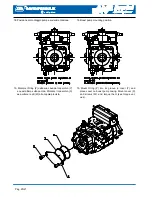
Page 18: ...o sulla pompa Montare le viti 37 con le ron delle 113 Avvitare le viti 37 alla coppia prevista AT TENZIONE usare frenafiletti medio LOCTITE 243 sulle viti Montare i tappi 52 e la tar ghetta 58 con i r...

Page 19: ...6 e linguetta 75 Montare targhetta rotazione 49 con rivetti 91 17 Mount Oring 79 into its groove in pump casing Mount flange 98 Mount Oring 79 and gerotor set 20 on boost pump casing 21 Mount boost pu...

Page 20: ...r on boost pump casing Mount cover X and screws W and torque them see torque val ues 18 Posizione di montaggio pompa sovralimentazione 19 Montare l Oring Z nella sua cava del coperchio Y e quest ultim...

Page 21: ...anche quelli gi ordina ti senza notifica Notice Due to the continuous product developments modifications and improvements S A M Hydraulik Spa will not be held responsible for any erroneous information...

Reviews: