31
Communication and Monitoring
Table 7
RS485 Pin Definition
Pin
1
2
3
4
Function
TX+
TX-
RX+
RX-
●
Connections
Figure 24
4-line RJ11
Table 8
4-line RJ11
4-line RJ11 Wire No.
Wire Color
1
Brown
2
White Brown
3
Orange
4
White Orange
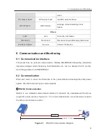
Connect the system as blow (Figure25), you can easily monitoring the PV power station.
Figure 25
SolarPower Manager Monitoring Diagram
Select high-quality network cable, peel the isolation surface, Select 4 wires ( brown, white brown,
orange, white orange), then follow the same order with the press pliers push into the 4-wire RJ11
crystal head.
PC
RS485
Hub
Internet
LAN
LAN
Ethernet
SolarPower Manager

