background image

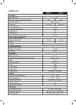
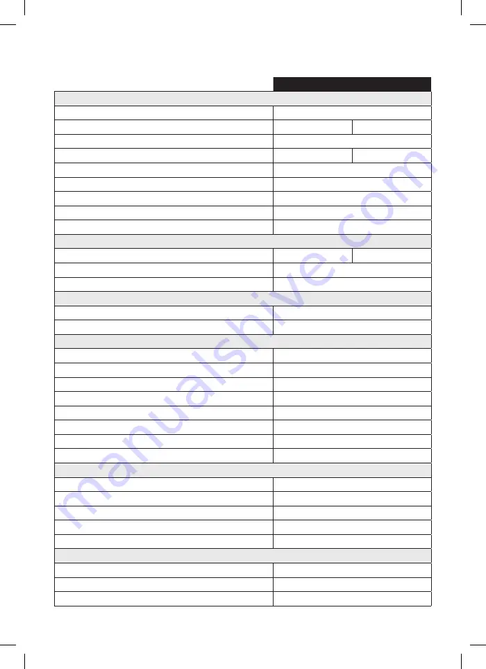
TECHNICAL DATA

BGW-40

BGW-60

ELECTRICAL

Input voltage range

6 … 35 V

Maximum continuous output current (@25 °C)

40 A

60 A

Peak current (@25 °C)

300 A (± 0.7 sec)

Voltage drop

40 mV @ 40 A

60 mV @ 60 A

Current Output active

3.2 mA

Consumption Output inactive

3.2 mA

Voltage accuracy

2%

Current accuracy

10%

Maximum status/alarm output load

100 mA

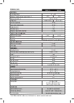
INPUT & OUTPUT CONNECTOIN

Minimum wire diameter

10 mm

2

16 mm

2

Bolt size

M6

Cable lugs

Cable lugs must match the cable diameter used.

FASTON CONNECTIONS

Minimum wire diameter

1.5 mm

2

Faston plug

6.3 mm

MECHANICAL

Mounting hole (Ø)

4.2 mm

Distance between mounting holes (centre to centre)

50 mm, ± 1 mm

Weight

155 g

Dimensions (H*W*L)

32*72*62 mm

IP Code

IP66

Housing material

PU552

Housing colour

Black

Cooling concept

Convection and conduction.

GENERAL

Operational ambient temperature

-10 °C  ... +40 °C

Storage temperature

-25 °C  ... +85 °C

Operational air humidity

Up to 95%, non-condensing.

Galvanic insulation

No

Remote contact switch-off

Yes

PROTECTION

Overcurrent/Short circuit

Yes (after 1 minute restart).

Overheating, shutdown

Above 85 °C (after 1 minute restart).

Polarity protection

Yes, with fuse in the minus (-) line.

Summary of Contents for BGW-40

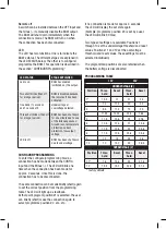
Page 1: ...n Use this connection only for the BGW WIRING DIAGRAM please see last page OPERATION Input voltage protection The input voltage protection values undervoltage threshold undervoltage reset overvoltage...

Page 2: ...and the Minus The LED will blink one time when the connection has been made for approx 2 seconds Once this is done the connection has to be disconnected The same connection can be made briefly short...

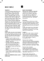
Page 3: ...nexion n gative Utilisez cette connexion uniquement pour le BGW SCH MA DES CONNEXIONS Veuillez consulter la derni re page MODE DE FONCTIONNEMENT Protection contre la surtension d alimentation L utilis...

Page 4: ...CONFIG et la borne n gative La LED 1 se met clignoter d s qu un contact a t tabli pendant 2 secondes D s que cela se produit le contact doit tre rompu Pour programmer le num ro de position ad quat il...

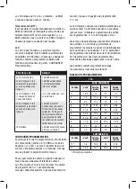
Page 5: ...N Por favor vea la ltima p gina FUNCIONAMIENTO Protecci n de la tensi n entrada El usuario puede configurar los valores de la protecci n de la tensi n de entrada umbral de subtensi n reseteo de subten...

Page 6: ...se una conexi n entre la entrada de CONFIG y el min Una vez se haya establecido la conexi n durante 2 segundos el LED parpadear una vez Tan pronto como esto ocurra deber interrumpirse la conexi n A fi...

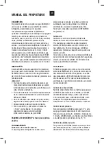
Page 7: ...FASTON CONNECTIONS Minimum wire diameter 1 5 mm2 Faston plug 6 3 mm MECHANICAL Mounting hole 4 2 mm Distance between mounting holes centre to centre 50 mm 1 mm Weight 155 g Dimensions H W L 32 72 62...

Page 8: ...ole 4 2 mm Distance between mounting holes centre to centre 50 mm 1 mm Weight 155 g Dimensions H W L 32 72 62 mm IP Code IP66 Housing material PU552 Housing colour Black Cooling concept Convection and...

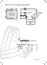
Page 9: ...0 60 1222 50 mm 36 mm 36 mm REMOTE OFF CONFIG STATUS ALARM FUSE 1A FUSE LOAD BATTERY Battery Guard Models BGW 40 BGW 60 Please read this manual BEFORE operating the units Owner s Manual 11004 BGW 40 6...

Reviews: