background image

16  |  SAMLEX AMERICA INC.    


SAMLEX AMERICA INC.  |  17

APPENDIX A

SECTION 4  |  

Parameter Setup

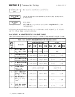
9

“BATT LOW VOLTAGE”

(Battery Low Voltage 

Shut Down)

>9.0V – 12.0V

>18.0V – 24.0V

10.5V

21.0V

10

“LV DETECT TIME”

(Detect Time to Qualify 

as Battery Low Voltage 

Shut Down Condition)

0-600 sec

10 sec

11

“LV CUT OFF TIME”

(Time in Low Voltage 

Shut Down Condition 

before Shut Down is 

Activated)

0-7200 sec

1200 sec

12

“CHARGE MODE”

(3 or 4 Stage Charging)

Normal (3-Stage) / 

Equalization (4-Stage)

0 = Normal (3-Stage)

13

"ON-LINE MODE"

 or 

"OFF-LINE"

0 = OFF (Off-Line: Grid/Generator Priority)

1 = ON (On-Line Mode: Battery/Invertor Priority)

14

"RECONNECT VOLT"

(For On-Line Mode)

13.50V – 16.00V

27.00V – 32.00V

14.00V

27.60V

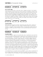
BULK CURRENT:

This sets the maximum charging current of EVO Inverter Charger. This value is the sum of 
charging currents from the internal AC Charger and external Charge Controller connected to 
the EXT. Charger terminals of EVO Inverter Charger (3,4 Fig 2.1 in Owner's Manual for EVO 
Inverter Charger).

SELECT GROUP

CHARGE CURVE

BULK CURRENT

40 A

Enter Key

ò

ABSORP VOLTAGE:

This sets the charging voltage in the Constant Voltage Absorption Stage.

SELECT GROUP

CHARGE CURVE

BULK CURRENT

40 A

ABSORP VOLTAGE

13.80 V

Enter Key

ò

Up Key x 1

ò

EQUALIZE VOLTAGE:

This sets the charging voltage in the Constant Voltage Stage in the 4-stage Equalization 
Charging Stage.

SELECT GROUP

CHARGE CURVE

BULK CURRENT

40 A

EQUALIZE VOLTAGE

14.60 V

Enter Key

ò

Up Key x 2

ò

FLOATING VOLTAGE:

This sets the charging voltage in the Constant Voltage Float Stage.

SELECT GROUP

CHARGE CURVE

BULK CURRENT

40 A

FLOATING VOLTAGE

13.50 V

Enter Key

ò

Up Key x 3

ò

Summary of Contents for Evolution EVO-2212

Page 1: ...EvolutionTM Series Inverter Charger Pure Sine Wave Models EVO 2212 EVO 3012 EVO 2224 EVO 4024 Please read this manual BEFORE operating Owner s Manual ...

Page 2: ...Components Layout 24 SECTION 3 Installation 28 SECTION 4 General Description and Principles of Operation 59 SECTION 5 Battery Charging in Evolution Series 70 SECTION 6 Operation Protections and Troubleshooting 78 SECTION 7 Specifications 85 SECTION 8 Warranty 88 APPENDIX A EVO RC Optional Remote Control Owner s Manual ...

Page 3: ...une risque de faire des dégâts à l équipement si l utilisateur ne suit pas les instruc tions i INFO Indicates useful supplemental information Please read these instructions BEFORE installing or operating the unit to prevent per sonal injury or damage to the unit WARNING 1 DANGER To reduce risk of explosion do not install in machinery space or in area in which ignition protected equipment is requir...

Page 4: ...lectric shock and fire Installation should be carried out by certified installer and as per Local and National Electrical Codes Do not connect to circuit operating at more than 150 Volts to Ground Do not connect to AC Load Center Circuit Breaker Panel having Multi wire Branch Circuits connected Both AC and DC voltage sources are terminated inside this equipment Each circuit must be individually di...

Page 5: ... Column 1 Programmed Input Cur rent Limit Column 2 NEC Ampac ity 125 of Column 2 Column 3 Size based on NEC Am pacity at Column 3 and 75 C Copper Conductor in Conduit Column 4 Breaker Size Based on NEC Am pacity at Column 3 Column 5 EVO 2212 30A Default 37 5A AWG 8 40A EVO 2224 EVO 3012 EVO 4024 TABLE 1 1 b AC INPUT WIRING AND BREAKERS FOR AC INPUT CURRENT LIMIT PROGRAMMED AT 45A FOR EVO 3012 AND ...

Page 6: ... ft EVO 2212 AWG 3 0 AWG 4 0 350A EVO 2224 AWG 2 AWG 2 175A EVO 3012 2 X AWG 3 0 MCM 300 2 X AWG 3 0 MCM 300 500A EVO 4024 AWG 3 0 AWG 4 0 350A External Charger AWG 6 AWG 2 70A TABLE 1 3 B BATTERY CABLES IN RACEWAY AND EXTERNAL BATTERY SIDE FUSES Item Copper 90 C Fuse Up to 5 ft Up to 10 ft EVO 2212 2 X AWG 4 0 MCM 350 2 X AWG 4 0 MCM 350 350A EVO 2224 AWG 1 0 AWG 1 0 175A EVO 3012 Not recommended...

Page 7: ...onnement des disjonc teurs pour les circuits de sortie AC Codes électriques nationaux et locaux remplaceront ces lignes directrices 8 Les bornes de la batterie sont conçus pour se connecter sur le terrain avec des conducteurs en cuivre qui sont dimensionnés en fonction de 90 C et sont plus grandes que AWG n 1 42 4 mm2 Voir les tableaux 1 3 a et 1 3 b pour les tailles recommandées pour l installati...

Page 8: ...rre de la batterie Assurez vous que tous les accessoires sont hors de sorte que vous ne causent pas une étincelle 1 2 DEFINITIONS The following definitions are used in this manual for explaining various electrical concepts specifications and operations Peak Value It is the maximum value of electrical parameter like voltage current RMS Root Mean Square Value It is a statistical average value of a q...

Page 9: ...is denoted as P and the unit is Watt It is the power that is consumed in the resistive elements of the load A load will require additional Reactive Power for powering the inductive and capacitive elements The effective power required would be the Apparent Power that is a vectorial sum of the Active and Reactive Powers Reactive Power Q VAR Is denoted as Q and the unit is VAR Over a cycle this power...

Page 10: ...amps and Quartz heaters These require higher starting surge power due to lower resistance value when the heating elements are cold Reactive Load A device or appliance that consists of a combination of resistive inductive and capacitive elements like motor driven tools refrigeration compressors microwaves comput ers audio video etc These devices require Apparent Power VA from the inverter to operat...

Page 11: ...requencies These capacitors are used in ballasts for fluorescent lighting for Power Factor improvement and in single phase induction motors as start and run capacitors Thus modified and square wave inverters may shut down due to overload when powering these devices 1 3 2 Advantages of Pure Sine Wave Inverters The output waveform is a sine wave with very low harmonic distortion and cleaner power li...

Page 12: ...ctive Power in VAR and is Active Power in Watts Power Factor Thus for such reactive loads higher sized inverter is required based on the Apparent Power Further all reactive types of loads require higher inrush starting surge power that may last for 1 to 5 sec and subsequent lower running power If the inverter is not sized adequately based on the type of AC load it is likely to shut down or fail pr...

Page 13: ...unintentional and cannot be entirely eliminated The magnitude of EMI is however limited by circuit design to acceptable levels as per limits laid down in North American FCC Standard FCC Part 15 B Class B These limits are designed to provide reasonable protection against harmful interference when the equipment is operated in a residential environment These inverters can conduct and radiate radio fr...

Page 14: ...ther due to the presence of high value of input filter capacitors the current drawn by an SMPS With no Power Factor correction is not sinusoidal but non linear as shown in Fig 1 3 The steady state input current of SMPS is a train of non linear pulses instead of a sinusoidal wave These pulses are two to four milliseconds duration each with a very high Crest Factor corresponding to peak values aroun...

Page 15: ...Factor of current drawn by SMPS 1 4 GENERAL INFORMATION LEAD ACID BATTERIES INFO For complete background information on Lead Acid Batteries and Charging Process visit www samlexamerica com Support White Papers Whitepaper Batteries Chargers and Alternators Lead acid batteries can be categorized by the type of application 1 Automotive service Starting Lighting Ignition SLI a k a cranking and 2 Deep ...

Page 16: ...he rated capacity C in Ah in this case will be the number of Amperes of current the battery can deliver for 20 Hours at 80ºF 26 7ºC till the volt age drops to 1 75V Cell i e 10 5V for 12V battery or 21V for 24V battery For example a 100 Ah battery will deliver 5A for 20 Hours 1 4 3 Rated Capacity Specified in Reserve Capacity RC Battery capacity may also be expressed as Reserve Capacity RC in minu...

Page 17: ...ATE CAPACITY C in Ah DISCHARGE TIME T Table 1 8 below gives some examples of C Rate specifications and applications TABLE 1 8 DISCHARGE CURRENT RATES C RATES Hours of discharge time T till the End Point Voltage C Rate Discharge Current in Amps Capacity C in Ah Discharge Time T in Hrs Example of C Rate Discharge Currents for 100 Ah battery 0 5 Hrs 2C 200A 1 Hrs 1C 100A 5 Hrs Inverter application C ...

Page 18: ...gher capacity loads the usable Ah capacity reduces due to Peukert Effect This relationship is not linear but is more or less according to the Table 1 9 SECTION 1 Safety Instructions General Information Typical Flooded Lead Acid Battery Chart 80 F 26 7 C Battery Voltage in VDC Battery State of Charge in Percent 0 10 20 30 40 50 60 70 80 90 100 110 120 130 16 5 16 0 15 5 15 0 14 5 14 0 13 5 13 0 12 ...

Page 19: ...Amperes 1 Hour 1 4 8 State of Charge SOC of a Battery Based on Standing Voltage The Standing Voltage of a battery under open circuit conditions no load connected to it can approximately indicate the State of Charge SOC of the battery The Standing Voltage is measured after disconnecting any charging device s and the battery load s and let ting the battery stand idle for 3 to 8 hours before the volt...

Page 20: ...ery The terminal voltage of the battery is dependent upon the following Temperature of the battery electrolyte Temperature of the electrolyte affects the electro chemical reactions inside the battery and produces a Negative Voltage Coefficient during charging discharging the terminal voltage drops with rise in temperature and rises with drop in temperature The amount of discharging current or C Ra...

Page 21: ... with a protection to shut down the output of the inverter if the DC voltage at the input terminals of the inverter drops below a threshold of around 10V for a 12V battery 20V for 24V battery Referring to the Discharge Curves given in Fig 1 4 the State of Discharge for various C Rate discharge currents for battery voltage of 10V 20V is as follows Please note that the X Axis of the curves shows the...

Page 22: ...or an inverter running from a 12V battery system the DC current required from the 12V batteries is the AC power delivered by the inverter to the load in Watts W divided by 10 for an inverter running from a 24V battery system the DC current required from the 24V batteries is the AC power delivered by the inverter to the load in Watts W divided by 20 3 Energy required from the battery DC current to ...

Page 23: ...ed by the load was 300 Ah FOR 24V BATTERY 250 Ah 0 8 312 5 Ah Note that the actual energy required was 150 Ah It will be seen from the above that the final rated capacity of the batteries is almost 2 times the energy required by the load in Ah Thus as a Rule of Thumb the Ah capacity of the bat teries should be twice the energy required by the load in Ah 1 14 15 Charging Batteries Batteries can be ...

Page 24: ...ck for Temperature Sensor EVO BCTS Fig 2 5 7 RJ 45 Jack for EVO RC Remote 8 Air inlet vents for 2 internal cooling fans Additional air inlet vents at the bottom not shown 9A 9B RJ 45 Jacks for Communication Ports COMM 1 and COMM 2 For RS 485 networking and MODBUS Serial Communication Protocol for future use 9C 9D RJ 45 Jacks for Communication Ports COM 3 and COM 4 For CANbus Serial Communi cation ...

Page 25: ...Input Output Terminals behind cover plate 1 3 AC Input Output Terminal Block Terminal hole diameter 6mm for up to AWG 6 Set Screw M4 4 Grid Input Line 5 Grid Input Ground 6 Grid Input Neutral 7 Generator Input Line 8 Generator Input Ground 9 Generator Input Neutral 10 AC Output Line 11 AC Output Ground 12 AC Output Neutral 13 Male Female Insulated Quick Disconnect for disabling Output Neutral to C...

Page 26: ...D Alarm Fault 5 Navigation Key Back 6 Navigation Key Up 7 Navigation Key Down 8 Navigation Key Enter 9 SD Card Slot FAT16 32 format Up to 16GB 10 RJ 45 Jack At the back not shown 11 RJ 45 Data Cable Straight Wired 10 meter 33 feet length Fig 2 4 b 2 4 REMOTE CONTROL EVO RC FIG 2 4 OPTIONAL Fig 2 4 a Optional Remote Control EVO RC Fig 2 4 b Cable for Remote Control ...

Page 27: ... suitable for 3 8 or 5 16 battery studs 2 RJ 45 Plug 3 5 meter 16 5 ft cable Note Mount the sensor on the Positive or Negative terminal stud on the battery as shown in Fig 2 5 b 3 1 2 2 6 CONTENTS OF PACKAGE Inverter Charger Temperature Sensor EVO BCTS Fig 2 5 a DC Terminal Covers 1a 1b Fig 2 1 Fitted on the unit with 2 screws each Mating Connectors 14 15 16 Fig 2 1 Wire End Terminals Fig 3 11 a O...

Page 28: ...y requirements the mounting has to satisfy the following requirements Mount on a non combustible material The mounting surface should be able to support a weight of at least 60 Kg 132 lbs Use 4 pcs of 1 4 or M6 mounting bolts and lock washers Cooling The unit has openings on the front bottom and back for cooling and ventilation Ensure that these openings are not blocked or restricted Install in co...

Page 29: ...izontally on a vertical surface like a wall with the fan axis horizontal and the DC input terminals facing left Please see Fig 3 3 Fig 3 3 Mounting Arrangement 1 On Vertical Surface CAUTION Ensure there is OVER 200 mm clear space surrounding the inverter for ven tilation ATTENTION Assurer qu il y a PLUS QUE 200 mm d espace DÉGAGÉ entourant l onduleur pour faciliter la ventilation SECTION 3 Install...

Page 30: ...ed voltage and capacity 3 4 1 Series Connection Fig 3 5 Series Connection When two or more batteries are connected in series their voltages add up but their Ah capacity remains the same Fig 3 5 shows 4 pieces of 6V 200 Ah batteries connected in series to form a battery bank of 24V with a capacity of 200 Ah The Positive terminal of battery 4 becomes the Positive terminal of the 24V bank The Negativ...

Page 31: ... connection becomes the Negative terminal of the 12V battery bank 3 4 3 Series Parallel Connection Fig 3 7 Series Parallel Connection Figure 3 7 shows a series parallel connection consisting of four 6V 200 Ah batteries to form a 12V 400 Ah battery bank Two 6V 200 Ah batteries Batteries 1 and 2 are connected in series to form a 12V 200 Ah battery String 1 Similarly two 6V 200 Ah batteries Batteries...

Page 32: ... at the same charging discharging cur rent and thus will be charged discharged to the same state at the same time None of the batteries will see an overcharge overdischarge condition If the Positive output cable of the inverter charger Cable A is connected to the Positive battery post of the first battery Battery 1 in Fig 3 6 or to the Positive battery post of the first battery string Battery 1 of...

Page 33: ...même courant ainsi elles seront rechargées à l état pareille au même temps Aucune des batteries auront une condition de surcharge Si le câble positif de sortie du chargeur de batterie Câble A est lié à la borne positive de la première batterie La batterie 1 dans la Fig 3 6 ou à la borne positive de batterie qui est liée au premier fil Le fil 1 et La Batterie 1 Fig 3 7 et puis le câble négatif de s...

Page 34: ...ections are required to be made see Fig 3 8 Deep cycle batteries are connected to the battery input terminals 1 and 2 The termi nals are provided with protective covers RED for Positive and BLACK for Negative Fit these covers once connections have been made For details on sizing and charging of batteries please refer to Section 1 4 under General Information Lead Acid Batteries Use appropriate exte...

Page 35: ...l produce sparking on the last contact in the input loop even when the unit is in powered down condition Ensure that the fuse is inserted only after all the connections in the loop have been completed so that sparking is limited to the fuse area Flow of electric current in a conductor is opposed by the resistance of the conductor The resistance of the conductor is directly proportional to the leng...

Page 36: ... bon côté Lié le positif de la batterie à la borne positive de l appareil et le négatif de la batterie à la borne négative de l appareil Si les polarité de l entrée sont mise à l envers le fusible CC externe du côté d entrée va s exploser et peut causer des dégâts permanent à l onduleur ATTENTION La section d entrée de l onduleur a des condensateurs de grande valeur qui sont connecté aux bornes d ...

Page 37: ...t pas marcher et même seront endommager Circuit de rechargement de batterie PV La perte de tension pourrais causer une perte de puissance disproportionée Par exemple une perte de tension à 5 peut réduire le courant de charge par une pourcentage beaucoup plus grande que 5 3 5 4 Fuse Protection In The Battery Circuit A battery is an unlimited source of current Under short circuit conditions a batter...

Page 38: ...que for the nut is 70 kgf cm 5 lbf ft Sizes of cables and fuses are shown in Table 3 1 Sizing is based on safety considerations specified in UL 1741 and NEC 2014 See details under Notes for Table 3 1 3 5 6 DC Input Connection for External Charger External charger is connected to terminals consisting of M12 Stud with Thumb Nut 3 4 in Fig 5 3 Max current fed through these terminals should be 50A Use...

Page 39: ...AWG 2 2 voltage drop is thicker 70A NOTES FOR TABLE 3 1 SIZING OF BATTERY SIDE CABLES AND EXTERNAL BATTERY SIDE FUSES 1 Column 2 indicates the Rated Continuous DC Input Current drawn from the battery in Inverter Mode 2 Column 3 indicates NEC Ampacity based on which cable conductor sizes Columns 5 to 8 are determined NEC Ampacity is not less than 125 of the Rated Continuous DC Input Current Column ...

Page 40: ...NEC 2014 National Electrical Code Section 240 4 B d Type of fuse Fast acting Current Limiting UL Class T UL Standard 248 15 or equivalent 3 5 7 Using Proper DC Cable Termination The battery end and the inverter end of the wires should have proper terminal lugs that will ensure a firm and tight connection Choose lugs to fit the wire size and the stud sizes on the inverter and battery ends 3 5 8 Red...

Page 41: ...Terminal Block Terminal hole diameter 6mm for up to AWG 6 Set Screw M4 4 Grid Input Line 5 Grid Input Ground 6 Grid Input Neutral 7 Generator Input Line 8 Generator Input Ground 9 Generator Input Neutral 10 AC Output Line 11 AC Output Ground 12 AC Output Neutral 13 Male Female Insulated Quick Disconnect for disabling Ouptut Neutral to chassis Ground bond in Inverter Mode Please see Section 4 5 1 t...

Page 42: ...ur décharge obtient lié au châssis métallique de l unité à travers la interne Neutre à châssis relais de commutation Dans Mode de chargement l interne Neutre à châssis relais de commutation déconnecte le neutre de la connexion de sortie AC du châssis de l unité Le neutre de la connexion de sortie CA de l unité va obtenir lié à la terre des masses à travers le neutre à la terre liaison au sol dans ...

Page 43: ...que du disjoncteur Pour éviter possibilité de mise en parallèle et de graves dommages à l onduleur ne jamais utiliser un câble de raccordement simple avec une fiche mâle sur les deux extrémités pour raccorder la sortie AC de l onduleur à une prise murale à portée de main à la maison RV 3 6 4 Connecting to Multi wire Branch Circuits DO NOT directly connect the Hot side of the 120 VAC of the unit to...

Page 44: ...n de la grille générateur est reliée aux bornes d entrée de courant alternatif et non aux bornes de sortie à courant alternatif et que cette connexion est établie uniquement lorsque l appareil est dans un état hors tension Se il vous plaît noter que lorsque l appareil est sous tension un auto test est effectué qui inclut un contrôle si la tension d entrée CA de la connexion réseau générateur a été...

Page 45: ...NTION Breakers AC pour les circuits d entrée AC ont pas été fournis en interne Ceux ci doivent être fournies à l extérieur par l installateur utilisateur sur la base des directives données ci dessous Se il vous plaît noter que les directives ci dessous sur dimensionnement des câbles et protection contre les surintensités seront remplacées par les nationaux codes électriques locaux applicables 3 8 ...

Page 46: ... rameter Select for Input Settings Max Current All the 4 models EVO 2212 2224 3012 and 4024 come with Input Current Limit set at 30A Default Setting See Table 3 2 1 Higher Power Models will require higher Amp rating of the Generator the Grid Branch Circuit Wiring and breaker sizing for Input Current Limit at 45A for EVO 3012 4024 is given at Table 3 2 2 and for 60A for EVO 4024 is given at Table 3...

Page 47: ...onductor Size Based on NEC Ampacity at Column 6 See Note 6 Column 7 External Breaker Size Based on NEC Ampacity at Column 6 See Note 7 Column 8 EVO 4024 4000VA 33A 33 33A 29A 62 33A 60A 75A AWG 4 or 2 x AWG 6 80A NOTES FOR TABLES 3 2 1 3 2 2 and 3 2 3 SIZING OF GRID AND GENERATOR INPUT WIRING AND BREAKERS 1 Column 2 indicates the Rated AC Pass Through Current when in Charger Pass Through Mode valu...

Page 48: ...er has been used Refer to NEC 2014 National Electrical Code Section 240 4 B regarding over current devices d Type of breaker Standard circuit breaker for 120VAC Load Center Breaker Panel 3 9 SIZING OF WIRING AND BREAKERS AC OUTPUT SIDE WARNING AC Breakers for the AC output circuits have NOT been provided internally These have to be provided externally by the installer user based on guidelines give...

Page 49: ...e load side Hence the AC out put circuit of the unit is considered to be a Feeder Circuit for purposes of NEC 2014 3 Column 4 indicates conductor size for the output side wiring The size is based on NEC 2014 National Electrical Code Ampacity Table 310 15 B 16 for Raceway Conductor size is based on i NEC Ampacity Column 3 ii conductor temperature of 75 C and iii ambient temperature of 30 C 86 F 4 C...

Page 50: ...Home Support White Papers Grounded Electrical AC Power Distribution System Grounding System and Lightning Ground Fault Protection 3 12 GROUNDING ARRANGEMENT IN EVO SERIES Schematic at Fig 3 12 illustrates the grounding arrangement of EVO Series Internally EVO consists of a DC Section and an AC Section that are isolated through a trans former Both these sections are required to be grounded appropri...

Page 51: ...el The Bus Bar G3 for Equipment Grounding Conductors of the AC Distribution Panel is con nected to the Bus Bar for the Equipment Grounding Conductors G3 of the Grid Generator Input Panel which in turn is connected to the Ground Rod or the Grounding Electrode GE Thus in keeping with the NEC requirements the AC Grounds of EVO and the AC Distribution Panel will be bonded to the Earth Ground only at o...

Page 52: ...nded to the Earth Ground at one single point at the location of the AC Power Distribution System of the Marina RV Park Disabling Neutral to Ground Bond In some applications the Output Neutral may be required to remain isolated from the chassis Ground at all times For this automatic Ouput Neutral to Chassis Ground bond can be disabled by disconnecting the Male Female Quick Disconnect located in the...

Page 53: ...ds fed by EVO B N G3 G1 SBJ G2 4 5 6 7 8 9 10 11 12 13 GE Neutral Bus bar Bus bar for Equipment Grounding Conductors EGC A C Ground of EVO System Bonding Jumper SBJ Grounding Terminal on EVO 5 Fig 3 8 GRID LINE GRID GND GRID NEUTRAL GENERATOR LINE GENERATOR GND GENERATOR NEUTRAL OUTPUT LINE OUTPUT GROUND OUTPUT NEUTRAL Quick Disconnect Ground Electrode Ground Rod Breaker 120 VAC Leg Phase A 120 VA...

Page 54: ...nnected to the DC input provided for external battery charger AC input to the EVO is fed from the Grid and Generator Panel AC output from the EVO is fed to the AC Distribution Panel Automatic Generator start stop is possible as follows Start operation is initiated by contact closure of the Status Relay 14 Fig 2 1 when battery voltage drops to the programmed value of the Low Voltage Alarm Stop sequ...

Page 55: ...e Battery Negative External Charger Positive External Charger Negative Grounding Terminal RF 45 Jack for Temperature Sensor RJ 45 Jack for Optional Remote Control EVO RC Status Relay Terminals for initiating automatic generator start stop 4 5 6 7 8 9 10 11 12 AC SIDE GRID LINE GRID GND GRID NEUTRAL GEN LINE GEN GND GEN NEUTRAL OUTPUT LINE OUTPUT GND OUTPUT NEUTRAL A B N NG G GE GRID PANEL AC DISTR...

Page 56: ...s use lots of thin plates to maximize the surface area of the plates for providing very large bursts of current also specified as Cranking Amps This allows very high starting current but causes the plates to warp when the battery is cycled Vehicle starting typically discharges 1 3 of a healthy SLI battery s capacity The automotive SLI battery is not designed for repeated deep discharge where up to...

Page 57: ...lation using 30A Service Inlet for 30A RV Power Supply Cord Auxiliary Battery is connected to the DC input connections through an appropriate fuse to protect the DC input cables against short circuit Auxiliary battery will be charged by the alternator through the Battery Isolator Battery Temperature Sensor Model BTS EVO is installed on the Positive or Negative post of the auxiliary battery and con...

Page 58: ...ord To Loads Optional Remote Control EVO RC LINE To Remote Start Stop Terminals on the Generator Optional Generator Auto Start Stop Module 1 2 3 4 5 6 7 14 DC SIDE Battery Positive Battery Negative External Charger Positive External Charger Negative Grounding Terminal RJ 45 Jack for Temperature Sensor RJ 45 Jack for Optional Remote Control EVO RC Status Relay Terminals for initiating automatic gen...

Page 59: ...ional external charging source like Solar Charge Controller AC charger of up to 50A capacity The output of the external charging source is routed through this unit and operates in parallel with the internal charger The internal charging current is controlled to ensure that the combined current fed to the battery does not exceed the programmed Bulk Charging Current This improves the life of the bat...

Page 60: ... load current The output voltage recovers automatically when power drawn by the load drops below the above surge limits Power Boost up to 150 Higher percentage of rated power can be provided for limited time periods as follows 150 for 5 sec 140 for 30 sec 120 for 5 min 110 for 30 min 4 4 DIRECT DUAL AC INPUT ARCHITECTURE For higher reliability and redundancy direct AC input from Grid and Generator...

Page 61: ...nverter Charger This will ensure that the Grounded Conductor GC Neutral of the Grid power Generator is bonded to the Earth Ground at one single point at the location of the AC Power Distribution System of the Marina RV Park Disabling Neutral to Ground Bond In some applications the Output Neutral may be required to remain isolated from the chassis Ground at all times For this automatic Output Neutr...

Page 62: ... the output Neutral OUTPUT NEUTRAL gets bonded to the chassis of the unit through the mated contacts of the Insulated Quick Disconnect QD located in the AC Wiring Compartment 13 Fig 3 9 4 5 3 Operation of Transfer and Output Neutral to Chassis Ground Bond Switching Relays EVO 3012 and EVO 4024 Refer to Schematic at Fig 4 1 b The Bi directional Transformer is used as follows o Feeds AC output from ...

Page 63: ...over to contacts 1 and 3 respectively Neutral output from the Inverter Section is fed the Neutral of the Bi directional Transformer and onwards to the output Neutral OUTPUT NEUTRAL for powering the AC loads At the same time the output Neutral OUTPUT NEUTRAL gets bonded to the chassis of the unit through the mated contacts of the Insulated Quick Disconnect QD located in the AC Wiring Compartment 13...

Page 64: ...hen both Grid and Generator are available simultaneously Grid has priority To facilitate synchronization transfer of power from Grid to Generator or from Generator to Grid is always routed through the inverter 4 5 5 Transfer From Inverter to Grid Generator When Grid Generator becomes available its voltage and frequency are checked if these are within the programmed limits If yes the output voltage...

Page 65: ... AC Power Source to PWM controlled low voltage DC to charge the DC Battery Source That is why it is called a Bi directional device Normal 3 Stage Charging Mode consists of Bulk Absorption and Float stages Default 4 Stage Equalization Mode consists of Bulk Absorption Equalization and Float The Equalization Mode is selectable Equalization Mode is desirable for the proper health of Wet Cell Batteries...

Page 66: ...ll the sections inside the unit alive and ready to deliver power to the AC load as soon as the load is switched on This power is called the No Load Power Draw or the Idle Power or Self Power Consumption The No Load Power Draw of these units in the Normal Mode is around 25W to 30W The EVO has a provision to minimize this No Load Power Draw if required Applicable only when the unit is in Inverter Mo...

Page 67: ...e Default Mode In this Mode PRIORITY is given to the AC input fed from the Grid Generator Inputs This is the Default Mode If qualified AC input within the programmed voltage and frequency limits is available at the Grid Generator AC inputs Transfer Relay energizes and the unit operates in Charging Mode and qualified AC input from the Grid Generator is passed through to the AC Output and at the sam...

Page 68: ...ee Appendix A Range is 3 to 4 mv C cell Default is 4 mv C cell Without temperature compensation the battery life is likely to be drastically reduced be cause the battery will be undercharged during cold conditions will build up sulfation or will be overcharged during hot conditions will boil and lose excessive water Please read White Paper titled Batteries Chargers Alternators available online at ...

Page 69: ...Data Logging using SD Card of up to 16 GB FAT16 FAT32 It also has its own Real Time Clock and Super Capacitor Type of Inter nal Battery The Remote Control will be required for Firmware upgrade through the SD Card Detailed messaging is available through its LCD display and LEDs This remote will also be required for programming of various parameters to suit specific requirements Each pro grammable p...

Page 70: ...roller based 3 Stage or a 4 Stage Charger Battery charging parameters are detailed at Table 5 1 3 Stage Charging Algorithm Default is used for normal day to day charging The 3 stages are Bulk Absorption and Float The charging voltages and currents are programmable within the ranges given in the Table 5 1 to take care of a wide range of battery types like flooded AGM Gel Cell Lead Calcium etc For d...

Page 71: ...ing source is routed through the unit Connectors 3 4 in Fig 2 1 Maximum charging cur rent from the external charging source is limited to 50A This limit should not be exceeded Please note that Lead Acid batteries should not be charged at very high charging currents to prevent adverse effects like reduction in returned capacity excessive surface charge overheat ing excessive pressure build up in se...

Page 72: ...nt is delivered to the batteries until the battery voltage approaches its Gassing Voltage Absorption Voltage typically around 14 4 volts for 12 volt batteries and 28 8 volts for 24 volt batteries again this voltage can vary based upon the desired values programmed through the Parameter Setting Menu of the optional Remote Control Model EVO RC see Appendix A The Bulk Charge Stage restores about 75 o...

Page 73: ...Parallel Please note that if an external charging source is also used to charge the batteries at the same time in parallel with the internal AC charger of the unit the charging current of the internal AC charger will be controlled so that the total charging current of the external charger and the internal charger is the programmed Bulk Charging Current Io For example if the programmed charging cur...

Page 74: ...lles gelées et aussi souvent que les recommandations du fabricant 4 Stage Battery Charging Cycle is used in the Equalization Mode Equalization Mode is selected using optional Remote Control EVO RC see Appendix A Equalization of the batteries is car ried out periodically normally once per month for battery under heavy duty service and every two to four months for battery under light duty service As...

Page 75: ...he Standing Voltage Terminal Voltage after disconnecting charging source s and load s for at least 3 hours at 20 capacity will be o 12V Battery Around 11 7V o 24V Battery Around 23 4V Do not equalize partially or fully charged batteries ATTENTION Pour une égalisation efficace il faut que les batteries subissent à une étape majeure plus long en fonction de la condition déchargée de la batterie Veui...

Page 76: ...n Stage it transitions to the programmed Equalization Voltage see programmable range and defaults at Table 5 1 It remains in this stage for the computed time T2 This stage is displayed as E CVE in the Charging Mode screens in Remote Control EVO RC Appendix A The equalization current I2 is normally 5 to 10 of the Ah capacity of the battery This current is indirectly computed from the programmed Bul...

Page 77: ...reen LED Status will return to 1 flash per second To terminate Equalization Mode prematurely before its completion press the ON OFF Push Button for 1 second If the unit was in Inverting Mode Green LED Status steady and the Mode is set to Equal ization as above by pressing the ON OFF Push Button for 1 second the unit will undergo Equalization Mode whenever qualified AC input is available from Grid ...

Page 78: ...the unit is NOT in Standby Mode by pressing ON OFF Button briefly Standby Mode is used for Firmware upload through the optional Remote Control EVO RC see Appendix A o If LED marked ON 12 Fig 2 1 stays OFF then unit is OFF o If this LED is ON or is flashing the unit was in Standby Mode and is now ON 6 1 POWERING ON USING ON OFF BUTTON ON THE FRONT PANEL 11 Fig 2 1 6 1 1 Powering ON To power ON the ...

Page 79: ... Logic used is as follows When the unit is in OFF condition toggling the external manual switch to ON position or closing the external relay contact will immediately turn the unit ON When the unit is in ON condition toggling the external manual switch to OFF position for 2 seconds or opening the relay contact for 2 sec will turn the unit OFF CAUTION When Switch Type of ON OFF control described abo...

Page 80: ...ing Please see separate Owner s Manual for EVO RC at Appendix A The Remote Control comes with 10M 33 ft RJ 45 Data Cable The Remote plugs into RJ 45 Jack on the front panel of the unit 7 Fig 2 1 It has provision for Data Logging using SD Card of up to 16 GB FAT16 FAT32 It also has its own Real Time Clock and Super Capacitor Type of Bat tery Detailed messaging is available through its LCD display a...

Page 81: ...V 30 0V 13 8V 27 0V COMPENSATE Temperature Compensation 3mV to 5mV C Cell 4mV C Cell LOW VOLT ALARM Battery Low Voltage Alarm 9 5V 12 5V 19 0V 25 0V 11 0V 22 0V BATT LOW VOLTAGE Battery Low Voltage Shut Down 9 0V 12 0V 18 0V 24 0V 10 5V 21 0V LV DETECT TIME Low Voltage Detect Time 0 600 sec 10 sec LV CUT OFF TIME Low Voltage Cut Off Time 0 7200 sec 1200 sec RESET VOLTAGE Battery Low Voltage Reset ...

Page 82: ... EVO 4024 INPUT LOW LIMIT RESET VOLTAGE 60 0 200 0V 95 0V CUT OFF POINT 1 60 0 200 0V 90 0V DETECT TIME 1 0 2000 cycle 300 cycle CUT OFF POINT 2 60 0 200 0V 85 0V DETECT TIME 2 0 2000 cycle 60 cycle CUT OFF POINT 3 60 0 200 0V 80 0V DETECT TIME 3 0 2000 cycle 1 cycle TABLE 6 5 PROGRAMMABLE AND DEFAULT PARAMETERS GROUP INPUT HIGH LIMIT Group Parameter name Setting range Default value EVO 2212 EVO 3...

Page 83: ...ting is Button Type If the ON OFF Control is changed to external Remote Switch it will not be possible to switch ON OFF the EVO Inverter Charger from the front panel ON OFF Push Button because it will work with Switch Type Logic It will be ON only as long as the Push Buttom is kept pressed and will switch OFF when released RELAY FUNCTION 0 Relay will be ON contacts will close when in Charging Mode...

Page 84: ...resent the unit CANNOT BE POWERED OFF using the ON OFF Button on the front panel of the unit or on the optional Remote Control EVO RC see Appendix A In order to power off using the Power ON Off Button switch OFF the AC input first 6 7 12V 100mA CAPACITY DC SOURCE FOR SIGNALING A 12V 100mA capacity DC source has been provided 16 Fig 2 1 This voltage may be routed through the contacts of the Status ...

Page 85: ...0 3800W 140 3080W 140 5600W Power Boost for 5 min 120 2640W 120 3400W 120 2640W 120 4800W Power Boost for 30 min 110 2420W 110 3200W 110 2420W 110 4400W Maximum Continuous DC Input Current 266 A 373 A 133 A 266 A Inverter Efficiency Peak 90 90 93 94 No Load Power Consumption in Power Saving Mode 8 W No Load Power Consumption in Normal Mode 120 VAC Output Typical 30 watts 25 watts AC INPUT FROM GRI...

Page 86: ...l Mode 3 Stages Bulk Absorption and Float Equalization Mode 4 Stages Bulk Absorption Equalization and Float Adaptive Charging Control Battery Temperature Compensa tion Battery Temperature Sensor included Compensation Range from 20 C to 60 C EXTERNAL BATTERY CHARGER SECTION Solar Charge Controller Charging Voltage Range 13 15VDC 13 15VDC 26 30VDC 26 30VDC Maximum Charging Current 50A COOLING PROTEC...

Page 87: ...ure 20 C to 60 C 4 F to 140 F Storage Temperature 40 C to 70 C 40 F to 158 F Operating Humidity 0 to 95 RH non condensing WEIGHTS AND DIMENSIONS Dimensions W x D x H 325 x 426 x 207 mm 12 79 x 16 77 x 8 15 in Weights 27 Kg 59 lb 29 kg 64 lb 26 Kg 57 lb 29 Kg 64 LB NOTE 1 All AC power ratings in the Inverter Section are specified at Power Factor 0 95 2 All specifications given above are at Ambient ...

Page 88: ... serial number that has been altered removed or modified in any way There is no warranty for defects or damages to equipment or parts caused by Installation alternation inspection or removal Normal wear and tear Abuse or misuse of the equipment including exposure to excessive heat salt or fresh water spray or water immersion Corrosion fire lightening biological infestations or Acts of God Repairs ...

Page 89: ...SAMLEX AMERICA INC 89 Notes ...

Page 90: ...90 SAMLEX AMERICA INC Notes ...

Page 91: ...SAMLEX AMERICA INC 91 Notes ...

Page 92: ...5885 Fax 888 814 5210 Local Numbers Ph 604 525 3836 Fax 604 525 5221 Website www samlexamerica com USA Shipping Warehouse Kent WA Canadian Shipping Warehouse Delta BC Email purchase orders to orders samlexamerica com 11025 EVO 2212 3012 2224 4024 0215 ...

Page 93: ...trol for Evolution Series Inverter Charger Model EVO RC Please read this manual BEFORE operating Owner s Manual APPENDIX A NOTE REMOTE CONTROL MODEL NO EVO RC IS OPTIONAL AND IS REQUIRED TO BE ORDERED SEPARATELY ...

Page 94: ...ons Introduction and Layout 3 SECTION 2 Installation 4 SECTION 3 Operation 6 SECTION 4 Parameter Setup 11 SECTION 5 SD Card 30 SECTION 6 Monitoring of Operation Using LED and Buzzer 35 SECTION 7 Fault Messages and Troubleshooting Guide 36 SECTION 8 Specifications 39 SECTION 9 Warranty 40 ...

Page 95: ...own in Fig 1 1 a and b below RJ 45 Plug 11 Fig 1 1 b Cable For Remote Control EVO RC 1 LCD Screen 2 rows of 16 characters each 2 ON OFF Key 3 Green LED Status 4 Red LED Alarm Fault 5 Navigation Key Back 6 Navigation Key Up 7 Navigation Key Down 8 Navigation Key Enter 9 SD Card Slot FAT16 32 for mat Up to 16 GB 10 RJ 45 Jack At the back not shown 11 RJ 45 Data Cable Straight Wired 10 meter 33 feet ...

Page 96: ...lips Head Screwdriver Level Hand Drill Knife Saw Pencil Drill Bit 2 5mm 39 Fig 2 1 EVO RC Remote Cutout Dimensions 2 2 FLUSH MOUNT INSTALLATION To flush mount the wall opening must have at least a 2 5 cm depth to make room for the remote and cable Also the thickness of wall panel board at the place of mounting should not be more than 13 mm to ensure that the RJ 45 jack opening is not obstructed se...

Page 97: ...initiates 6 If the self test is successful secure the EVO RC to the wall using the four screws Fig 2 2 The thickness of the wall panel board at the place of mounting should not be more than 13mm to ensure that the RJ 45 jack opening is not obstructed Fig 2 3 Wall Panel Thickness RJ 45 Jack WALL PANEL BOARD Flush mounting the EVO RC on the wall with 4pcs Φ3mm self tapping screws flat head Fig 2 2 E...

Page 98: ...ults also appear on the LCD display ON OFF Key 2 The ON OFF Key is used for switching ON switching OFF the EVO Inverter Charger Navigation Keys 5 6 7 8 These four Keys allow simple access to menu items that assists configuring monitoring and troubleshooting the EVO Inverter Charger o Navigation Key Functions Back Return to previous selection Up Move to upper Group Number or upper Page Number Scree...

Page 99: ...how POWER OFF and both the Status and Alarm LEDs will turn ON Now release the ON OFF key Please note that Power Off sequence will be completed and display POWER OFF will disappear only when the ON OFF key is released NOTE If the EVO Inverter Charger has AC input voltage over 60VAC the Power OFF function is disabled and the unit will remain in the ON condition if the power off sequence is attempted...

Page 100: ...V CHARGING INPUT 1 120 00V N CC Fig 3 1 EVO RC Mode Screens 3 6 1 Charging Mode Screens Explanations Please refer to 18 Screens shown against Pages 1 to 18 under Group 3 CHARGING at Fig 3 2 The 1st line of the Display Screen for Charging Mode shows CHARGING on the left and abbreviated information format Charging Mode Charging Stage on the right corner The following abbreviations have been used Abb...

Page 101: ...NG OUTPUT POWER SAVING ID 1 RC 007 CHARGING GEN Page 4 STANDBY GEN 0 00V INVERTING OUTPUT CHARGING GEN Page 5 STANDBY 2014 10 16 16 00 12 000V 140 0A 0 0A 25 0C 0 00V 0 00V RC XXX1 60 00Hz 10 00A 1200W 1200VA PF 1 000 INVERTING OUTPUT CHARGING INPUT 20 00A N CC2 Page 6 Page 7 Page 8 Page 9 Page 10 Page 11 Page 12 Page 13 Page 14 Page 15 Page 16 Page 17 Page 18 STANDBY ID 1 RC XXX1 INVERTING OUTPUT...

Page 102: ... Current CC Bulk Stage E CVA Constant Voltage Absorption CVA Stage E CVE Constant Voltage Equalization CVE Stage FLOAT Float Stage Float Stage 18 Screens Pages 1 to 18 for CHARGING Mode Column 4 Group 3 are shown as an ex ample for Bulk Charging Stage in Normal Charging Mode N CC Depending upon the Charg ing Mode and Stage the unit is in at any particular time 18 sets of screens will be seen for e...

Page 103: ...enus Groups 1 to 7 as shown in Parameter Setup Menu Maps at Fig 4 1 for Groups 1 to 4 and Fig 4 2 for Groups 5 to 7 For convenience each Parameter Setup Screen can be referenced by 2 co ordinates Group No Column and Page No Row NOTE The values of parameters shown in Figs 4 1 and 4 2 are the Default Values The desired Parameter Setup Screen can be reached by navigating through the Select Group Menu...

Page 104: ...80 V MAXIMUM CURRENT 30 00 A CUT OFF VOLT 1 140 0 V CUT OFF VOLT 1 90 0 V Page 3 EQUALIZE VOLTAGE 14 60 V HIGH CUT OFF 65 00 Hz DETECT TIME 1 60 cycles DETECT TIME 1 300 cycles Page 4 FLOATING VOLTAGE 13 50 V HIGH RESET 64 00 Hz CUT OFF VOLT 2 85 0 V Page 5 COMPENSATE 4 MV C C LOW CUT OFF 55 00 Hz DETECT TIME 2 60 cycleS Page 6 Page 7 Page 8 Page 9 Page 10 Page 11 Page 12 Page 13 Page 14 BATT OVER...

Page 105: ...with upward pointer because Page Nos in this Parameter Setting Menu Map decrease in the upward direction Page 1 Group 5 SELECT GROUP OTHER FUNCTION Group 6 SELECT GROUP TIME SETTING Group 7 SELECT GROUP STOP SD CARD POWER SAVING 1 Enable TIME SETTING 2000 01 01 00 00 STOP SD CARD 0 No BUZZER 1 On DISCHARGE BEEP 0 Off DEFAULT RESET 0 No DATA LOG TIME 1 1 sec PARAMETER SAVE 0 No Page 2 ENTER POINT 4...

Page 106: ...he mode associated with current operation It is highly recommended to set the EVO Date and Time Parameter Group 6 as this value is used to record data logging files Refer to Section 4 9 for Date and Time set up Group 1 Enter Key Back Key Any Operationg Mode Screen from Fig 3 2 Parameter Setup Screen eg BULK CURRENT Select Group Menu Map SELECT GROUP CHARGE CURVE BULK CURRENT 40 A INVERTING OUTPUT ...

Page 107: ...hort press of the Enter Key will confirm this value and move to the next digit to the right A long press of the Enter Key is used to write the parameter selection the Password in this case KEY IN PASSWORD 0000 SELECT GROUP CHARGE CURVE BULK CURRENT 40 A PASSWORD CORRECT PASSWORD ERROR BULK CURRENT 40 A BULK CURRENT 90 A WRITING 50 A WRITE SUCCESS 50 A WRITE FAILURE 50 A OUT OF RANGE 90 A BULK CURR...

Page 108: ... 4 4 GROUP 1 PARAMETER SET UP CHARGE CURVE Please refer to Parameters under Group 1 at Fig 4 1 Details of Parameter set up are given below TABLE 4 4 GROUP 1 PARAMETER SET UP CHARGE CURVE Page No for Group 1 Fig 4 1 Parameter Programming Range Default EVO 2212 EVO 3012 EVO 2224 EVO 4024 EVO 2212 EVO 3012 EVO 2224 EVO 4024 1 BULK CURRENT Bulk Charge Current Io 0 100A 0 130A 0 70A 0 110A 40A 2 ABSORP...

Page 109: ...rent of EVO Inverter Charger This value is the sum of charging currents from the internal AC Charger and external Charge Controller connected to the EXT Charger terminals of EVO Inverter Charger 3 4 Fig 2 1 in Owner s Manual for EVO Inverter Charger SELECT GROUP CHARGE CURVE BULK CURRENT 40 A Enter Key ò ABSORP VOLTAGE This sets the charging voltage in the Constant Voltage Absorption Stage SELECT ...

Page 110: ...p steady The fault will be cleared automatically when the battery voltage drops to 0 5V below the set upper threshold of BATT OVER VOLT AC input is available and EVO Inverter Charger is operating in Charging Mode When the battery voltage rises to the set upper threshold of BATT OVER VOLT the Trans fer Relay will be de energized charging and pass through will be stopped and PWM drive to the Inverte...

Page 111: ...erter Charger will beep steady If the Battery low voltage fault condition is not reset within the LV CUTOFF TIME the EVO Inverter Charger will be shut down completely after LV CUTOFF TIME has elapsed If the batteries are charged by external charger connected directly to the batteries or through the External Charger Input 3 4 in Fig 2 1 in EVO Inverter Charger Manual and the battery voltage recover...

Page 112: ...A CHARGE MODE 0 Normal Enter Key ò Up Key x 11 ò ON LINE MODE In this mode PRIORITY is given to the Inverter Section Even if qualified AC input within the programmed voltage and frequency limits is available at the Grid Generator AC inputs the unit always operates in Inverting Mode and AC output is provided by the Inverter Section as long as the battery is in charged condition above the LOW VOLT A...

Page 113: ...0 OFF SELECT GROUP CHARGE CURVE CHARGE CURVE BULK CURRENT ONLINE MODE 0 Off Enter Key ò Up Key x 12 ò RECONNECT VOLT As explained under ON LINE MODE above RECONNECT VOLT setting is the battery voltage at which the unit transfers from Charging Mode to Inverting Mode SELECT GROUP CHARGE CURVE CHARGE CURVE BULK CURRENT RECONNECT 14 00V Enter Key ò Up Key x 13 ò 4 5 GROUP 2 PARAMETER SET UP INPUT SETT...

Page 114: ...MAXIMUM CURRENT 30 00 A DEFAUT FREQ 0 60Hz Up Key ò Enter Key ò Up Key x 1 ò HIGH CUT OFF If the AC input frequency is over the value of HIGH CUT OFF when in Charging Mode the EVO Inverter Charger will transfer to Inverting Mode SELECT GROUP CHARGE CURVE SELECT GROUP INPUT SETTING HIGH CUT OFF 65 00 Hz DEFAUT FREQ 0 60 Hz Up Key ò Enter Key ò Up Key x 2 ò HIGH RESET This is the reset frequency at ...

Page 115: ...OFF VOLT 2 CUT OFF VOLT3 SELECT GROUP CHARGE CURVE SELECT GROUP INPUT LOW LIMIT RESET VOLTAGE 95 0 V Up Key x 2 ò Enter Key ò CUT OFF VOLT 1 If during Charging Mode the AC input voltage falls below CUT OFF VOLT 1 for period DETECT TIME 1 the EVO Inverter Charger will transfer to Inverting Mode from Charging Mode SELECT GROUP CHARGE CURVE SELECT GROUP INPUT LOW LIMIT CUT OFF VOLT 1 90 0 V RESET VOL...

Page 116: ...T DETECT TIME 3 1 cycle RESET VOLTAGE 95 0 V Up Key x 2 ò Enter Key ò Up Key x 6 ò 4 7 GROUP 4 PARAMETER SET UP INPUT HIGH LIMIT Please refer to Parameters under Group 4 at Fig 4 1 Details of Parameter set up are given below TABLE 4 7 GROUP 4 PARAMETER SET UP INPUT HIGH LIMIT Page No for Group 4 Fig 4 1 Parameter Setting range Default value 2212 3012 2224 4024 2212 3012 2224 4024 1 RESET VOLTAGE 1...

Page 117: ...sfer to Inverting Mode SELECT GROUP CHARGE CURVE SELECT GROUP INPUT HIGH LIMIT CUT OFF VOLT 2 145 0 V RESET VOLTAGE 135 0 V Up Key x 3 ò Enter Key ò Up Key x 3 ò DETECT TIME 2 This is the time limit in cycles up to which high AC input voltage CUT OFF VOLT 2 is allowed SELECT GROUP CHARGE CURVE SELECT GROUP INPUT HIGH LIMIT DETECT TIME 2 15 cycle RESET VOLTAGE 135 0 V Up Key x 3 ò Enter Key ò Up Ke...

Page 118: ...Y FUNCTION 0 Charge Other 1 Normal Fault 2 Generator 2 Generator 6 COMM ID 1 255 1 7 BUZZER 1 ON 0 OFF 1 ON 8 DISCHARGE BEEP 1 ON 0 OFF 0 OFF 9 DEFAULT RESET 0 No 1 Yes 0 No 10 DATALOG DISABLE DATALOG TIME 0 Disable 1 1 sec 3 30 sec 4 1 min 5 5 min 6 10 min 1 1 sec 11 PARAMETER SAVE 0 No 1 Yes 0 No POWER SAVING Enable or disable Power Saving Mode when in Inverting Mode SELECT GROUP CHARGE CURVE SE...

Page 119: ...er power ON 12VDC input 5 sec will have no effect After power ON 12VDC input 5 sec will switch OFF EVO Inverter Charger 12VDC input is available Power On No 12VDC input for 2 sec Off Fig 4 8 On Off Logic Diagram for Remote Switch Options CAUTION On Off Logic shown in Fig 4 8 also controls the operation of the On Off Button on the front panel of EVO Inverter Charger 11 Fig 2 1 in EVO Inverter Charg...

Page 120: ...TION COMM ID 1 POWER SAVING 1 Enable Up Key x 4 ò Enter Key ò Up Key x 5 ò BUZZER Set the buzzer ON OFF SELECT GROUP CHARGE CURVE SELECT GROUP OTHER FUNCTION BUZZER 1 ON POWER SAVING 1 Enable Up Key x 4 ò Enter Key ò Up Key x 6 ò DISCHARGE BEEP To select the buzzer ON OFF while in Inverting Mode SELECT GROUP CHARGE CURVE SELECT GROUP OTHER FUNCTION DISCHARGE BEEP 0 OFF POWER SAVING 1 Enable Up Key...

Page 121: ... ò 4 10 GROUP 7 PARAMETER SETUP STOP SD CARD Please refer to Parameter STOP SD CARD under Group 7 at Fig 4 2 Set up details are given below Once SD Card is being used it should be removed ejected only after the operation of the Card has been stopped as shown below and mesage Please remove SD Card appears If the SD card is not removed within 30 sec it will reset After the card is removed it reverts...

Page 122: ...er Other Functions See Section 4 8 and Table 4 8 under heading DATALOG TIME and DATALOG DISABLE When the SD card is inserted and Data Logging Function is enabled Default the EVO In verter Charger will start recording statistics and events on the card SD card detected V2 x xxGB SD card unusable SD card Read error SD card Write error SD card full F i l e c r e a t i ng Data log function has been ini...

Page 123: ...s contents opened with a general purpose Text Reader The First Row is Inverter Model the Second Row is the title of columns separate by TABLE 5 2 Contents of Data Log File Follow procedure given below to open Data Log Files in Excel Start Excel Click File Menu Button Microsoft Office Button on the left hand corner Click Open from the Drop Down Menu Navigate to the Directory where the Log Files dow...

Page 124: ...iles Click Open Button Bottom right corner of Fig 5 1 Text Import Wizard Step 1 will be shown Fig 5 2 Choose Delimited File Type Fig 5 2 Screen Shot of Step 1 of Text Import Wizard in Excel Text Import Wizard Step 2 will appear see Fig 5 3 Choose Semicolon and click Finish button ...

Page 125: ...DIX A Fig 5 3 Screen Shot of Step 2 of Text Import Wizard in Excel Data as in Fig 5 4 will be displayed on your Worksheet with the Log Data stored in Columns and Rows Fig 5 4 Screen Shot and Data Log Work Sheet SECTION 5 SD Card ...

Page 126: ...R FUNCTION PARAMETER SAVE 0 No POWER SAVING 1 Enable Up Key x 4 ò Enter Key ò Up Key x 10 ò Now select PARAMETER SAVE 1 Yes Saved file end PARAMETER SAVE 0 No The parameters will be saved and message PARAMETER SAVE 1 Yes Saved file end PARAMETER SAV 0 No will be seen and then the screen will revert to PARAMETER SAVE 1 Yes Saved file end PARAMETER SAVE 0 No 5 4 2 Uploading Saved Parameters If there...

Page 127: ...me per second OFF OFF Equalization charging Flash 2 times per second OFF OFF Inverting ON OFF Beep per 3 second Default OFF Low battery alarm ON Flash 1 time per second Beep per second Power saving Flash 1 time per 3 second OFF OFF Standby OFF OFF OFF Fault OFF ON ON NOTE Buzzer is available only in EVO Inverter Charger There is no buzzer in Remote Control EVO RC SECTION 6 Monitoring of Operation ...

Page 128: ...ult condition will be cleared While in Battery low voltage fault condition if AC input is made available be fore the expiry of LV CUT OFF TIME the Battery low voltage fault condition will be cleared The EVO Inverter Charger will restart in Inverter Mode synchro nize with the AC input and then transfer to the AC input at zero crossing It will now operate in Charging Mode Battery ultra low voltage E...

Page 129: ...hed in OFF condition and will require manual reset by powering OFF waiting for 1 minute and then powering ON again The set threshold of MAXIMUM CURRENT Section 4 5 should match the breaker capacity of the AC input source AC input Branch Circuit If AC input current capacity cannot be increased reduce the AC load BULK CURRENT Section 4 4 accordingly Output over current EVO Inverter Charger is in FAU...

Page 130: ...rger is in FAULT MODE because the main Bidirectional Transformer in the EVO Inverter Charger has overheated to 150 C The Green LED marked Status will be switched OFF and the Red LED marked Alarm will be steady ON The buzzer in EVO Inverter Charger will beep steady If in Inverting Mode Inverter Section will be switched OFF If in Charging Mode the Transfer Relay will be de energized and the Inverter...

Page 131: ...Rows 16 Character each Alpha Numeric LCD Display LED INDICATORS Green Status Red Fault Alarm INPUT OUTPUT CONNECTION CABLE SET RJ 45 Data Cable Straight Wired 10 Meters 33 ft ENVIRONMENT OPERATING TEMPERATURE RANGE 20 C to 60 C DIMENSIONS W X H X D MM 144 x 114 x 35 5 W X H X D INCHES 5 6 x 4 5 x 1 4 WEIGHT WEIGHT WITHOUT CABLE 0 2 kg 0 4 lb WEIGHT WITH CABLES 0 5 kg 1 2 lb ...

Page 132: ...l number that has been altered removed or modified in any way There is no warranty for defects or damages to equipment or parts caused by Installation alternation inspection or removal Normal wear and tear Abuse or misuse of the equipment including exposure to excessive heat salt or fresh water spray or water immersion Corrosion fire lightening biological infestations or Acts of God Repairs attemp...

Page 133: ...SAMLEX AMERICA INC 41 APPENDIX A Notes ...

Page 134: ...42 SAMLEX AMERICA INC APPENDIX A Notes ...

Page 135: ...SAMLEX AMERICA INC 43 APPENDIX A Notes ...
Page 136: ...800 561 5885 Fax 888 814 5210 Local Numbers Ph 604 525 3836 Fax 604 525 5221 Website www samlexamerica com USA Shipping Warehouse Kent WA Canadian Shipping Warehouse Delta BC Email purchase orders to orders samlexamerica com 11025 EVO RC 0215 ...

Reviews: