background image

10  |  SAMLEX AMERICA INC.    


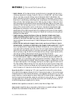
In a Sine Wave, the voltage rises and falls smoothly with a smoothly changing phase 
angle and also changes its polarity instantly when it crosses 0 Volts. In a Modified Sine 
Wave, the voltage rises and falls abruptly, the phase angle also changes abruptly and 
it sits at zero V for some time before changing its polarity. Thus, any device that uses a 
control circuitry that senses the phase (for voltage / speed control) or instantaneous zero 
voltage crossing (for timing control) will not work properly from a voltage that has a 
Modified Sine Waveform. 

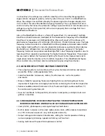
Also, as the Modified Sine Wave is a form of Square Wave, it is comprised of multiple 
Sine Waves of odd harmonics (multiples) of the fundamental frequency of the Modified 
Sine Wave. For example, a 60 Hz Modified Sine Wave will consist of Sine Waves with 
odd harmonic frequencies of 3rd (180 Hz), 5th (300 Hz), 7th (420 Hz) and so on. The high 
frequency harmonic content in a Modified Sine Wave produces enhanced radio interfer-
ence, higher heating effect in inductive loads like microwaves and motor driven devices 
like hand tools, refrigeration / air-conditioning compressors, pumps etc. The higher 
frequency harmonics also produce overloading effect in low frequency capacitors due to 
lowering of their capacitive reactance by the higher harmonic frequencies. These capaci-
tors are used in ballasts for fluorescent lighting for Power Factor improvement and in 
single-phase induction motors as Start and Run Capacitors. Thus, Modified and Square 
Wave inverters may shut down due to overload when powering these devices.

2.3  ADVANTAGES OF PURE SINE WAVE INVERTERS 

•  The output waveform is a Sine Wave with very low harmonic distortion and cleaner 

power like Utility / Grid supplied electricity. 

•  Inductive loads like microwaves, motors, transformers etc. run faster, quieter  

and cooler. 

•  More suitable for powering fluorescent lighting fixtures containing Power Factor 

Improvement Capacitors and single phase motors containing Start and Run Capacitors

•  Reduces audible and electrical noise in fans, fluorescent lights, audio amplifiers, TV, 

fax and answering machines, etc. 

•  Does not contribute to the possibility of crashes in computers, weird print outs and 

glitches in monitors.

2.4   SOME EXAMPLES OF DEVICES THAT MAY NOT WORK PROPERLY WITH 

MODIFIED SINE WAVE AND MAY ALSO GET DAMAGED ARE GIVEN BELOW: 

•  Laser printers, photocopiers, and magneto-optical hard drives. 

•  Built-in clocks in devices such as clock radios, alarm clocks, coffee makers, bread-mak-

ers, VCR, microwave ovens etc. may not keep time correctly. 

•  Output voltage control devices like dimmers, ceiling fan / motor speed control may 

not work properly (dimming / speed control may not function). 

•  Sewing machines with speed / microprocessor control. 

SECTION 2  |  

General Information

Summary of Contents for PST-150-12

Page 1: ...DC AC Power Inverter Pure Sine Wave PST 150 12 PST 150 24 Please read this manual BEFORE installing your inverter Owner s Manual ...

Page 2: ...NO WARRANTY AS TO THE ACCURACY SUFFICIENCY OR SUITABILITY OF ANY TECHNICAL OR OTHER INFORMATION PROVIDED IN ITS MANUALS OR OTHER DOCUMENTATION 2 ASSUMES NO RESPONSIBILITY OR LIABILITY FOR LOSSES DAMAGES COSTS OR EXPENSES WHETHER SPECIAL DIRECT INDIRECT CONSEQUENTIAL OR INCIDENTAL WHICH MIGHT ARISE OUT OF THE USE OF SUCH INFORMATION THE USE OF ANY SUCH INFORMATION WILL BE ENTIRELY AT THE USERS RISK...

Page 3: ...t personal injury or damage to the unit 1 2 SAFETY INSTRUCTIONS GENERAL Installation and wiring compliance Installation and wiring must comply with the Local and National Electrical Codes and must be done by a certified electrician Preventing electrical shock Always connect the grounding connection on the unit to the appropriate grounding system Disassembly repair should be carried out by qualifie...

Page 4: ... It could spark or short circuit the battery or other electrical parts and could cause an explosion Remove metal items like rings bracelets and watches when working with batteries The batteries can produce a short circuit current high enough to weld a ring or the like to metal and thus cause a severe burn If you need to remove a battery always remove the ground terminal from the battery first Make...

Page 5: ...ttery system Always use a Charge Controller between the solar panel and the battery Do not connect this unit to a battery system with a voltage higher than the rated bat tery input voltage of the unit e g do not connect PST 150 12 to 24V or 48V battery system or PST 150 24 to the 48V Battery System Preventing Reverse Polarity on the Input Side When making battery connections on the input side make...

Page 6: ...ees by which the current vector leads or lags the voltage vector in a sinusoidal voltage In a purely induc tive load the current vector lags the voltage vector by Phase Angle φ 90 In a purely capacitive load the current vector leads the voltage vector by Phase Angle φ 90 In a purely resistive load the current vector is in phase with the voltage vector and hence the Phase Angle φ 0 In a load consis...

Page 7: ...the net value of this power is 0 However on an instantaneous basis this power has to be provided by the AC source Hence the inverter AC wiring and over cur rent protection devices have to be sized based on the combined effect of the Active and Reactive Powers that is called the Apparent Power Apparent S Power VA This power denoted by S is the vectorial sum of the Active Power in Watts and the Reac...

Page 8: ...ist ance when cold and higher resistance when hot As Tungsten heating element will be cold at the time of powering ON its resistance will be low and hence the device will draw very heavy surge of current with consequent very heavy surge of power with a value of up to 8 times the Maximum Continuous Running AC Power AC to DC Switched Mode Power Supplies SMPS This type of power supply is used as stan...

Page 9: ...stive inductive and capacitive elements like motor driven tools refrigeration compressors microwaves computers audio video etc The Power Factor of this type of load is 1 e g AC motors PF 0 4 to 0 8 Transformers PF 0 8 AC to DC Switch Mode Power Supplies PF 0 5 to 0 6 etc These devices require Apparent Power VA from the AC power source The Apparent Power is a vectorial sum of Active Power Watts and...

Page 10: ... by the higher harmonic frequencies These capaci tors are used in ballasts for fluorescent lighting for Power Factor improvement and in single phase induction motors as Start and Run Capacitors Thus Modified and Square Wave inverters may shut down due to overload when powering these devices 2 3 ADVANTAGES OF PURE SINE WAVE INVERTERS The output waveform is a Sine Wave with very low harmonic distort...

Page 11: ...rge Power Rating to accommodate high short duration surge of power required during start up of certain AC appliances and devices Please read details of the above two types of power ratings in Section 2 1 under DEFINITIONS i INFO The manufacturers specification for power rating of AC appliances and devices indicates only the Maximum Continuous Running Power Rating The high short duration surge of p...

Page 12: ...candescent Halogen Quartz Lamps 3 Laser Printer Other Devices using Infrared Quartz Halogen Heaters 4 Switch Mode Power Supplies SMPS no Power Factor correction 2 Photographic Strobe Flash Lights 4 See Note 2 NOTES FOR TABLE 2 1 1 Multiply the Maximum Continuous Running Power Rating Active Power Rating in Watts of the appliance device by the recommended Sizing Factor to arrive at the Maximum Conti...

Page 13: ...ts of EMI will also depend upon a number of factors external to the inverter like proximity of the inverter to the EMI receptors types and quality of connecting wires and cables etc EMI due to factors external to the inverter may be reduced as follows Ensure that the inverter is firmly grounded to the ground system of the building or the vehicle Locate the inverter as far away from the EMI recepto...

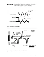
Page 14: ...on is not sinusoidal but non linear as shown in Fig 4 2 The steady state input current of SMPS is a train of non linear pulses instead of a sinusoidal wave These pulses are two to four milliseconds duration each with a very high Crest Factor of around 3 Crest Factor Peak value RMS value Many SMPS units incorporate Inrush Current Limiting The most common method is the NTC Negative Temperature Coeff...

Page 15: ...ate input RMS current NOTE Voltage and current scales are different Fig 4 1 Inrush current in an SMPS TIME Peak Current RMS Current Non linear Input Current Pulse Input Sine Wave Voltage Crest Factor Peak Current 3 RMS Current Voltage Voltage Current Current NOTE Voltage and current scales are different Fig 4 2 High Crest Factor of current drawn by SMPS ...

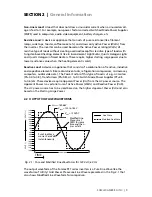
Page 16: ...egative direction and slowly increases in the Negative direction to a peak Negative value Vpeak 169 68V and then slowly drops back to 0V There are 60 such cycles in 1 sec Cycles per second is called the Frequency and is also termed Hertz Hz The Time Period of 1 Cycle is 16 66 ms TIME 0V Peak Negative Voltage VPEAK 169 68V VRMS 120 VAC Peak Positive Voltage VPEAK 169 68V Voltage Voltage 16 66 ms Fi...

Page 17: ...is behind this opening 5 Grounding Terminal 6 Positive DC Input Terminal 7 Negative DC Input Terminal 8 Air suction slots for cooling fan At the bottom Not shown PST 150 Back WARNING REVERSE POLARITY WILL DAMAGE THE UNIT AVERTISSEMENT INVERSION DE POLARITÉ PEUT ENDOMMAGER L UNITÉ 4 5 7 6 PST 150 Front 1 1 2 3 120VAC Fig 6 1 Layout of PST 150 12 and PST 150 24 6 1 FRONT AND BACK LAYOUTS ...

Page 18: ... second The Capacity C in Ah relates to the ability of the battery to provide a constant specified value of discharge current also called C Rate See Section 7 6 over a specified time in hours before the battery reaches a specified discharged terminal voltage Also called End Point Voltage at a specified temperature of the electrolyte As a benchmark the automotive battery industry rates batteries at...

Page 19: ...ove the amount of stored electrical energy is also called the Capacity of the battery and is designated by the symbol C The time in Hours over which the battery is discharged to the End Point Voltage for purposes of specifying Ah capacity depends upon the type of application Let us denote this discharge time in hours by T Let us denote the discharge current of the battery as the C Rate If the batt...

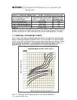
Page 20: ...rrent at 20 Hour discharge period i e C 20 Amps 7 7 CHARGING DISCHARGING CURVES Fig 7 1 shows the charging and discharging characteristics of a typical 12V 24V Lead Acid battery at electrolyte temperature of 80 F 26 7 C The curves show the State of Charge X axis versus terminal voltage Y axis during charging and discharging at different C Rates Please note that X axis shows State of Charge State o...

Page 21: ...s 50W output for a 12V inverter and 100W output for a 24V inverter However if it is discharged at a rate of 50 Amperes 500W output for a 12V inverter and 1000W output for a 24V inverter then theoretically it should provide 100 Ah 50 2 Hours However Table 7 3 shows that for 2 Hours discharge rate the capacity is reduced to 50 i e 50 Ah Therefore at 50 Ampere discharge rate 500W output for a 12V inv...

Page 22: ...allow a negligible voltage drop between the battery and the inverter Inverters are provided with a buzzer alarm to warn that the loaded battery has been deeply discharged to around 80 of the rated capacity Normally the buzzer alarm is triggered when the voltage at the DC input terminals of the inverter has dropped to around 10 5V for a 12V battery or 21V for 24V battery at C Rate discharge current...

Page 23: ... 24 3V 11 75V 23 5V In the example given above the 10 5V 21 0V Low Battery DC Input Alarm would trig ger at around 80 discharged state 20 SOC when the C Rate discharge current is C 5 Amps However for lower C Rate discharge current of C 10 Amps and lower the battery will be almost completely discharged when the alarm is sounded Hence if the C Rate discharge current is lower than C 5 Amps the batter...

Page 24: ...erter from excessive current drawn at the lower voltage 7 13 USE OF EXTERNAL PROGRAMMABLE LOW VOLTAGE DISCONNECTS The above ambiguity can be removed by using an external programmable Low Voltage Disconnect where more exact voltage threshold can be set to disconnect the battery based on the actual application requirements Please consider using the following Programmable Low Battery Cut off Battery ...

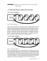
Page 25: ...erminal of Battery 2 The Negative terminal of Battery 2 is connected to the Positive terminal of Battery 1 The Negative terminal of Battery 1 becomes the Negative terminal of the 24V battery bank 7 15 2 Parallel Connection 12V Battery 1 Battery 3 Battery 2 Battery 4 12V 12V 12V Cable A Cable B 12V Inverter or 12V Charger Fig 7 3 Parallel Connection When two or more batteries are connected in paral...

Page 26: ...ner in which the charger inverter is connected to the battery bank Please ensure that if the Positive output cable of the battery charger inverter Cable A is connected to the Positive battery post of the first battery Battery 1 in Fig 7 3 or to the Positive battery post of the first bat tery string Battery 1 of String 1 in Fig 7 4 then the Negative output cable of the battery charger inverter Cabl...

Page 27: ...ce or equipment In case AC watts W are not indicated For mula 1 given above may be used to calculate the AC watts The next step is to estimate the DC current in Amperes A from the AC watts as per Formula 2 above An example of this calculation for a 12V inverter is given below Let us say that the total AC Watts delivered by the inverter 1000W Then using Formula 2 above the approximate DC current to...

Page 28: ...charging return of 100 capacity of Sealed Lead Acid Battery it is recommended that a 3 Stage Charger may be used Constant Current Bulk Charging Stage Constant Voltage Boost Absorption Charging Constant Voltage Float Charging In case Wet Cell Flooded Batteries are being used a 4 stage charger is recommended Constant Current Bulk Charging Stage Constant Voltage Boost Absorption Stage Constant Voltag...

Page 29: ...nst fire hazard The unit is not ignition protected and should not be located under any circumstance in an area that contains highly flammable liquids like gasoline or propane as in an engine compartment with gasoline fueled engines Do not keep any flammable combustible material i e paper cloth plastic etc near the unit that may be ignited by heat sparks or flames Closeness to the battery bank Locate...

Page 30: ...DIMENSIONS The overall dimensions and the location of the mounting slots are shown in Fig 8 1 155 65 5 187 127 30 1 5 30 145 5 5 1 5 5 211 22 7 5 155 Fig 8 1 PST 150 12 PST 150 24 Overall Dimensions Mounting Slots SECTION 8 Installation ...

Page 31: ...r down As explained above this is to prevent falling of objects into the unit through the fan opening when the fan opening faces up If fan opening faces down hot damaged component may fall out 8 4 DC SIDE CONNECTIONS 8 4 1 Preventing DC Input Over Voltage It is to be ensured that the DC input voltage of this unit does not exceed 16 5 VDC for PST 150 12 or 33 0 VDC for PST 150 24 to prevent permane...

Page 32: ...ternal Fuses WARNING The input section of the inverter has large capacitors connected across the input terminals As soon as the DC input connection loop Battery terminal External fuse Positive input terminal of the inverter Negative input terminal of the inverter Battery terminal is completed these capacitors will start charging and the unit will momentarily draw very heavy current that will produ...

Page 33: ...e drop can cause a dis proportionate loss of charge current to charge a battery A voltage drop greater than 5 can reduce charge current to the battery by a much greater percentage 8 4 4 Fuse Protection In Battery Circuit A battery is an unlimited source of current Under short circuit conditions a battery can supply thousands of Amperes of current If there is a short circuit along the length of the...

Page 34: ...OTES FOR TABLE 8 1 1 The Ampere Carrying Capacity Ampacity of various sizes of cables Columns 4 to 6 is based on ISO 10133 for single insulated conductors rated at 105 C and installation in free air at 30 C ambient temperature 2 Column 3 shows the minimum Ampacity of cable sizes as per the National Electrical Code NEC This is 1 25 times the maximum DC input current at the rated output power Column...

Page 35: ...feed this panel as backup power source the AC power from the utility power generator and the inverter should first be fed to a manual selector switch Automatic Transfer Switch and the output of the manual selector switch Automatic Transfer Switch should be connected to the electrical Panelboard Load Center 2 To prevent possibility of paralleling and severe damage to the inverter never use a simple...

Page 36: ...eutral of the inverter through internal Neutral to the chassis Ground bond and will shut down the inverter due to overload short circuit protection of the inverter 8 8 REDUCING ELECTROMAGNETIC INTERFERENCE EMI Please comply with recommendations given in Section 3 2 SECTION 9 Operation 9 1 SWITCHING THE INVERTER ON OFF Before switching on the inverter check that all the AC loads have been switched ...

Page 37: ...down When the temperature of this hot spot reaches 48 C the fan is switched ON The fan will be automatically switched OFF once the hot spot cools down to 42 C Please note that the fan may not come ON at low loads or if the ambient temperature is cooler This is normal 9 4 INDICATIONS FOR NORMAL OPERATION When the inverter is operating normally and supplying AC load s the Status LED 2 Fig 6 1 will b...

Page 38: ...DC INPUT VOLTAGE The voltage at the DC input terminals of the inverter will be lower than the voltage at the battery terminals due to voltage drop in the battery cables and connectors The drop in the voltage at the DC input terminals of the inverter could be due to drop in battery terminal voltage or due to abnormally high drop in the battery cables if the cables are not thick enough Please see de...

Page 39: ...re that the AC loads are connected through a 2 pole 3 Wire Grounding type of cord with a NEMA5 15P 3 Pin Plug This will provide protection against electric shock in case of Ground Fault in the load Line voltage leaking to the metal chassis of the load Fault current will flow through the Grounding Conductor to the chassis of the inverter and onward to the Neutral of the inverter through internal Ne...

Page 40: ... read Section 11 Troubleshooting Guide for more details CAUTION Damage caused by reverse polarity is not covered by warranty When making battery connections on the input side make sure that the polarity of battery connections is correct Connect the Positive of the battery to the Positive termi nal of the unit and the Negative of the battery to the Negative terminal of the unit If the input is conn...

Page 41: ...t 80VAC No buzzer alarm AC Load is exceeding 200 Surge Overload or 110 to 115 continu ous overload Low DC input voltage when supplying high AC loads approaching 110 to 115 continuous overload Check that the battery is fully charged Re charge if low Check that the battery cables are thick enough to carry the required current over the required length Use thicker cables if required Tighten connection...

Page 42: ...s not suitable as it requires higher power to operate Use an inverter with higher power rating If the unit goes into permanent overload again after resetting and removing the load com pletely the unit has become defective Call Technical support NOTE The unit will be latched in this shut down condition and will require manual reset To reset switch OFF the power ON OFF switch wait for 3 minutes and ...

Page 43: ... GROUND FAULT SHUTDOWN Yes Load should be powered using power cord with NEMA5 15P plug See Section 10 6 of Owner s Manual OVER TEMPERATURE SHUTDOWN At internal hot spot Temp of 95 C Auto reset at 70 C REVERSE POLARITY ON DC INPUT SIDE Internal DC side fuse will blow FORCED AIR COOLING Temperature Controlled Fan ON at internal hot spot 48 C OFF at 42 C INTERNAL DC SIDE FUSE Automotive Blade Type 32...

Page 44: ...e can supply this product without causing the vehicle fusing to open This can be determined by making sure that the fuse in the vehicle which protects the outlet is rated higher 20 Amperes 12V battery or 10 Amperes 24V battery Information on the vehicle fuse ratings is typically found in the vehicle operator s manual If a vehicle fuse opens repeatedly do not keep on replacing it The cause of the o...

Page 45: ...onable number of opportunities to do so Warranty service shall be performed only by the Warrantor Any attempt to remedy the defect by anyone other than the Warrantor shall render this warranty void There shall be no warranty for defects or damages caused by faulty installation or hook up abuse or misuse of the equipment including exposure to excessive heat salt or fresh water spray or water immers...

Page 46: ...e Numbers Ph 1 800 561 5885 Fax 1 888 814 5210 Local Numbers Ph 604 525 3836 Fax 604 525 5221 Website www samlexamerica com USA Shipping Warehouses Kent WA Plymouth MI Canadian Shipping Warehouse Delta BC Email purchase orders to orders samlexamerica com ...

Page 47: ...Veuillez lire les instructions trouvées dans ce manuel avant d installer votre onduleur Guide Du Propriétaire Onduleur de Puissance CC CA Onde Sinusoïdale Pure PST 150 12 PST 150 24 ...

Page 48: ...TÉ OU LA PERTINENCE DE TOUTE TECHNIQUE OU D AUTRES INFORMATIONS FOURNIES DANS SES MANUELS OU D AUTRES DOCUMENTS 2 N ASSUME AUCUNE RESPONSABILITÉ OU RESPONSABILITÉ POUR LES PERTES DOMMAGES COÛTS OU DÉPENSES QU IL S AGISSE DE PARTICULIERS DIRECTS INDIRECTS CONSÉCUTIFS OU ACCESSOIRES QUI POURRAIENT DÉCOULER DE L UTILISATION DE TELLES INFORMATIONS L UTILISATION DE CES RENSEIGNEMENTS SERONT ENTIÈREMENT...

Page 49: ...prévenir des blessures corporelles ou d endommager l appareil 1 2 CONSIGNES DE SÉCURITÉ GÉNÉRALES Installation et Conformité du Câblage L installation et le câblage doivent être conformes aux normes Électriques Locales et Nationales l installation doit être faite par un e électricien ne CERTIFIÉ E Prévention des Décharges Électriques Connectez toujours la connexion de terre de l appareil au systèm...

Page 50: ...mélange de gaz explosif lorsqu elles sont rechargées Ventilez à fond la zone de la batterie et suivez les recommandations du fabricant pour l emploi de la batterie Ne jamais fumer ni mettre une flamme à proximité des batteries Soyez prudent réduisez toute risque de chute d objets métalliques sur la batterie ce qui pourrait provoquer des étincelles ou court circuiter la batterie et les autres pièce...

Page 51: ...re non réglé pour recharger une batterie connectée à cet appareil À des températures ambiantes froides la sortie du panneau pourrait atteindre 22 VCC version de 12V ou 44 VCC version de 24V Utilisez toujours un contrôleur de charge entre la batterie et le panneau solaire Ne connectez pas l appareil à un système de batterie avec une tension plus forte que la tension d entrée de l appareil par exemp...

Page 52: ...sinusoïdale Rendement η Ceci est le rapport entre la Puissance de Sortie la Puissance d entrée Angle de Phase φ Cet angle est dénoté par φ et représente l angle en dégrés par lequel le vecteur de courant est en avance ou en retard comparé au vecteur de ten sion dans une tension sinusoïdale Pour les charges purement inductives le vecteur de courant est en retard du vecteur de tension par un Angle d...

Page 53: ...nsommé par ces éléments dans la charge mais une certaine valeur est envoyée de la source CA aux éléments pendant le demi cycle positif de la tension sinusoïdale Valeur Positive et la même valeur est renvoyée à la source CA pendant le demi cycle négatif la tension sinusoïdale Valeur Négative Donc quand on prend la moyenne sur la période d un cycle la valeur nette de cette puissance est 0 Néanmoins ...

Page 54: ...nner transformateur de puissance dans un four micro ondes etc Au moment où l alimentation CA est fournie à un transformateur le transformateur attire une puis sance très lourd de courant d appel de magnétisation pour quelques millisec qui peut atteindre jusqu à 10 fois la puissance continue maximale du transformateur Dispositifs comme réchauffeurs halogène en quartz à infrarouge également utilisé ...

Page 55: ...harge Résistive Un appareil ou dispositif qui comprend une résistance pure comme des lampes à filament brûleur grille pains cafetières etc et tire seulement la Puissance Active Watts de l onduleur L inverseur peut être dimensionné en fonc tion de la puissance active watts de type résistif de charges sans créer de surcharge à l exception de type résistif de charges avec élément de chauffage de tung...

Page 56: ...phase pour la tension contrôle de vitesse ou qui traverse 0 volts instantanément pour contrôler le temps ne va pas marcher avec une tension qui a une forme d onde sinusoïdale modifiée En plus l onde sinusoïdale modifiée a une forme carrée et est comprise d ondes sinusoïdales multiples bizarres et harmoniques d une fréquence fondamentale d onde sinusoïdale modifiée Par exemple une onde sinusoïdale ...

Page 57: ...réveils radio réveils cafetières ma chines à pain magnétoscopes fours à micro ondes etc ne pourraient pas fonctionner correctement Dispositifs de tension de sortie contrôlée comme des rhéostats ventilateur de plafond contrôle de vitesse moteur ne pourraient pas bien fonctionner variation de lumière ou le contrôle de vitesse ne marchent pas Machine à Coudre avec contrôle de vitesse contrôle micropr...

Page 58: ... le fabricant Ce n est peut être pas possible dans tous les cas et par conséquent peut être deviné au mieux basé sur certaines règles générales de pouce Le tableau 2 1 fournit une liste de certains appareils périphériques commun CA qui exigent de hautes surtension de courte durée pendant le démarrage Un facteur de di mensionnement onduleur a été recommandé contre chacune ce qui est un facteur de m...

Page 59: ...ge 4 Appareil à Découpage sans Amélioration du Facteur de Puissance 2 Stroboscope Lumières Éclatantes 4 Voir la Note 2 NOTES POUR LE TABLEAU 2 1 1 Multiplier la puissance nominale de fonctionnement continu maximum actif Puissance nominale en watts de l appareil périphérique par le facteur de dimensionnement recommandée pour arriver à la puissance nominale de fonctionnement continu maximum du conve...

Page 60: ...s facteurs externes comme la prox imité de l onduleur à des dispositifs réceptifs la qualité du câblage des câbles etc L IEM grâce à des facteurs externes peut être réduit en suivant les instructions ci dessous Assurez que l onduleur est connecté proprement au système de terre du batîment ou du véhicule Positionnez l onduleur le plus loin que possible des dispositifs qui sont sensibles à l IEM Il ...

Page 61: ... L état constant du courant d entrée d une alimentation à découpage est une suite d impulsions non linéaires au lieu d une onde sinusoïdale Ces impulsions sont deux à 4 millisecondes durée chaque avec un très haut facteur de crête d environ 3 facteur de crête Valeur de crête Valeur RMS Plusieurs Alimentations à Découpage incorporent une protection de réduction du surplus de courant Une méthode com...

Page 62: ...MARQUE Échelles de tension et de courant sont différents La Fig 4 1 Un Surplus de Courant d une Alimentation à Découpage TEMPS Courant d Entrée Non linéaire Tension d Entrée Onde Sinusoïdale Amplitude Courant MQ Factor de crête courant Pic 3 courant RMS REMARQUE Échelles de tension et de courant sont différents Voltage Voltage Courant Courant Fig 4 2 Facteur de Crête élevé du courant pris par l Al...

Page 63: ...ent à 0 V la polarité devient négative et monte dans la direction négative jusqu au pic Vpic 169 68V et ensuite descende doucement à 0 V Il y a 60 cycles pareils par seconde Le nombre de cycles par secondes est aussi appelé la Fréquence décrite en Hertz HZ La période du 1er cycle est 16 66 ms TEMP 0V Tension négative maximale VPIC 169 68V VRMS 120 VAC Pic de tension positive VPIC 169 68V Voltage V...

Page 64: ...4 Ouverture de Ventilation ventilateur de refroidissement est derrière cette ouverture 5 Ergot de Terre 6 Borne d entrée CC Positive 7 Borne d entrée CC Négative 8 Fentes de ventilation pour l apport d air en bas Non illustré PST 150 Le Derrière WARNING REVERSE POLARITY WILL DAMAGE THE UNIT AVERTISSEMENT INVERSION DE POLARITÉ PEUT ENDOMMAGER L UNITÉ 4 5 7 6 PST 150 Le Devant 1 1 2 3 120VAC ...

Page 65: ...ines ou batteries de voiturette de golf Utilisez des batteries à décharge profonde pour alimenter ces onduleurs 7 3 CAPACITÉ NOMINALE SPÉCIFIÉE EN AMPÈRES HEURES Ah La capacité de la batterie C est spécifié dans ampères heures Ah Un ampère est l unité de mesure pour le courant électrique et est défini comme une charge de Cou lomb passant par un conducteur électrique en une seconde La capacité C en...

Page 66: ...montre les détails de certaines tailles de batterie courantes TABLEAU 7 1 TAILLES DE BATTERIE COURANTES Groupe BCI Tension de la Batterie V Capacité de la Batterie Ah 27 31 12 105 4D 12 160 8D 12 225 GC2 6 220 Conseil international de la batterie Voiturette De Golf 7 6 SPÉCIFICATION DE CHARGE COURANT DE DÉCHARGE TAUX C L énergie électrique est conservé dans une cellule batterie sous forme de coura...

Page 67: ...teries 100Ah 0 5 Hrs 2C 200A 1 Hrs 1C 100A 5 Hrs L application de l onduleur C 5 or 0 2C 20A 8 Hrs Application UPS C 8 or 0 125C 12 5A 10 Hrs Application Telecom C 10 or 0 1C 10A 20 Hrs Application Automotive C 20 or 0 05C 5A 100 Hrs C 100 or 0 01C 1A REMARQUE Lorsque la batterie est déchargée sur une période plus courte son intensité de décharge spéci fiée C Taux sera plus élevé Par exemple le co...

Page 68: ...e le d état de charge L état de décharge sera 100 l état de charge Ces courbes seront mentionnées dans les explications suivantes Figue 7 1 Courbe de chargement déchargement pour Les accumulateurs au plomb Batterie au Plomb Acide 80 F 26 7 C TENSION DE BATTERIE EN VCC L État de la Batterie 0 10 20 30 40 50 60 70 80 90 100 110 120 130 16 5 16 0 15 5 15 0 14 5 14 0 13 5 13 0 12 5 12 0 11 5 11 0 10 5...

Page 69: ...outefois si elle est vidé à un taux de 50 ampères 500W de sortie pour un onduleur de 12V et une sortie de 1000W pour un onduleur de 24V théoriquement il devrait fournir 100 Ah 50 2 heures Toutefois le tableau 7 3 montre que pour 2 heures Taux de décharge la capacité est réduite à 50 c est à dire 50 Ah Par conséquent à un taux de 50 ampères de décharge 500 W de sortie pour un onduleur de 12V et 100...

Page 70: ...me l état de décharge de la batterie chargée en mesurant la tension aux bornes d entrée CC de l onduleur en considérant que les câbles d entrée CC sont suffisamment épaisse pour permettre une chute de tension négligeable entre la batterie et l onduleur Les onduleurs sont fournis avec un avertisseur sonore pour avertir que la batterie chargée a été complètement déchargée à environ 80 de la capacité...

Page 71: ...our les paramètres et les valeurs indiquées dans le tableau 7 5 TABLEAU 7 5 LA BORNE DE TENSION ET DE SOC DE BATTERIE CHARGÉE Décharge de Courant C Taux Tension au Bornes a 80 d état de décharge 20 SOC Tension Finale Lorsque complète ment déchargée 0 SOC 12V 24V 12V 24V C 3 A 10 45V 20 9V 09 50V 19 0V C 5 A 10 90V 21 8V 10 30V 20 6V C 10 A 11 95V 23 9V 11 00V 22 0V C 20 A 11 85V 23 7V 11 50V 23 0V...

Page 72: ...rme de tension d entrée CC bas fixe n est pas utile La température de la batterie complique davantage la situation Toutes les analyses ci dessus sont basées sur la température de l électrolyte de la batterie à 80 F La capacité de la batterie varie avec la température La capacité de la batterie est également une fonction de l âge et des rapports de charge Les batteries anciennes ont une capacité in...

Page 73: ...IES 7 15 1 Connexion en série Batterie 4 Batterie 3 Batterie 2 Batterie 1 Onduleur ou Chargeur de 24V 6V 6V 6V 6V Câble A Câble B Figure 7 2 Connexion en série Lorsque deux ou plusieurs batteries sont connectées en série leurs tensions s additionnent mais leur capacité en Ah ne change pas Figure 7 2 montre quatre morceaux de 6V batteries 200 Ah connectés en série pour former une banque de la batte...

Page 74: ...ve de la banque 12V De même les quatre terminaux négatifs des batteries 1 4 sont mis en parallèle reliés entre eux et cette connexion négative devient la borne négative de la banque de la batterie 12V 7 15 3 Série Connexion parallèle Ficelle 1 de 12V Ficelle 2 de 12V Batterie 1 Batterie 3 Batterie 2 Batterie 4 6V 6V 6V 6V Onduleur ou Chargeur de 12V Câble A Câble B Figure 7 4 Connexion série paral...

Page 75: ...r ies Cette question ne peut pas être répondue sans savoir la taille du système de batterie et la charge sur l onduleur Couramment cette question peut être redemande de suite Combien de temps voulez vous que votre charge fonctionne Et le calcul puis spéci fique peut être effectuée afin de déterminer la taille de la banque de batteries Il y a quelques formules de base et des règles d estimation qui...

Page 76: ...eront égal à POUR UNE BATTERIE 12V 500 Ah 0 8 625 Ah à noter que l énergie réelle requise par la charge était de 300 Ah POUR UNE BATTERIE 24V 250 Ah 0 8 312 5 Ah Notez que l énergie réelle requise était de 150 Ah On voit de ce qui précède que la capacité nominale finale des batteries est presque deux fois l énergie requise par la charge en Ah Ainsi en règle générale la capacité Ah des batteries do...

Page 77: ...z pas ces ouvertures ni installez l unité quelque par où la circulation d air est limitée Gardez 25cm d espace libre dans tous les sens autour de l unité afin d avoir une aération suffisante Si elle est installée dans un enclos des ouvertures doit être fournie pour ne pas bloquer l admission d air ni l échappement de l onduleur Sec Il faut que l unité soit à l abri de l eau de la consendation ou n...

Page 78: ... réceptacles CA et les connexions bornes de câblage CC bien dégagées car il va falloir les inspecter ou les ser rer de temps en temps Prévention de l Interférence de Fréquence Radio IFR Cette unité se sert des circuits de commutation à haute puissance qui génèrent de l IFR Ceci est limité en fonction des normes requises Situez des équipements électroniques susceptibles à IFR au plus loin possible ...

Page 79: ...GÉNÉRALES Les dimensions et la localisation des rainures de montage sont montrées dans la Fig 8 1 155 65 5 187 127 30 1 5 30 145 5 5 1 5 5 211 22 7 5 155 La Fig 8 1 Les Dimensions Générales et Rainures de Montages des PST 150 12 et PST 150 24 NB Dimensions en mm ...

Page 80: ...ertures sont mise sur l axe vertical Comme c est expliqué au dessus c est pour empêcher une chute d objet dans les ouvertures de ventilateurs lorsqu elles sont au dessus ou que des composants endommagés tombent par terre lorsqu elles sont en bas 8 4 CONNEXIONS DE CÔTÉ CC 8 4 1 Prévention d une Surtension de l Entrée CC Il faut assurer que la tension d entrée CC de cet appareil n excéde pas 16 5 VC...

Page 81: ... de l appareil Si les polarités de l entrée sont mises à l envers le fusible CC dans l onduleur va vont s exploser et pourrait causer des dommages permanents à l onduleur 8 4 3 La liaison entre les batteries et le côté d entrée DC de l unité Le dimensionnement des câbles et fusibles externe MISE EN GARDE La section d entrée de l onduleur a des condensateurs de grande valeur qui sont connectés aux ...

Page 82: ...la chaleur blanc à la chaleur RoUGE qui émet moins de lumière visible Circuits d allumage Fluorescent La perte de tension est presque proportionelle à la perte de lumière émise Moteurs à Induction CA Souvent Ils font partie des outils électriques des dispositifs pompe à puits etc Au démarrage ils exigent une surcharge de puissance Si la ten sion baisse de trop ils ne pourront pas marcher et même s...

Page 83: ... ducteurs en cuivre multibrin non recouverts à une température de 75 C 167 F Cette température est typique pour les circuits électriques TABLEAU 8 1 DES CÂBLES D ENTRÉE CC ET FUSIBLES No de Modèle 1 Courant d Entrée CC Maximal à la Puissance de Sortie Nominale 2 L intensité admissible minimale voir note 2 3 Taille de Câble basée sur la distance entre la batterie et le convertisseur voir notes 1 2 ...

Page 84: ...perte de puissance de la prise à environ 150W Quand vous faites marcher le PST avec la prise de 12V d un véhicule Veuillez assurer que la charge est limitée à 150W Une charge qui tire 150W explo sera le fusible de 15A dans le véhicule 8 5 CONNEXIONS DE CÔTÉ CA MISE EN GARDE Empêcher la Sortie CA de Se Mettre en Parallèle 1 La sortie CA de l appareil ne peut pas être synchronisée avec une autre sou...

Page 85: ... onduleur dans un mobile connectez RV 10 mm2 ou AWG 8 fil de cuivre multibrins isolés à partir de l équipement ci dessus cosse de mise à la terre appropriée du bus de terre RV habituellement le châssis du véhicule ou un bus de masse CC dédiées Les raccords doivent être serrés contre le métal nu Utiliser les rondelles en étoile pour pénétrer la peinture et la corrosion 8 7 INTERNE À LA MASSE DU CHÂ...

Page 86: ...arge 9 2 FAIRE MARCHER LES CHARGES Lorsque l onduleur est mis en marche celle ci prend une longue période de temps pour que la charge se mette en marche Donc faites marcher le s charge s quelques secondes après avoir allumer l onduleur Ne faites pas marcher l onduleur après que la charge soit déjà al lumée Ça pourrait prématurément déclencher la protection de surcharge Quand une charge est allumée...

Page 87: ... les protections suivantes 10 1 SURTENSION FERMETURE DE SURCHARGE COURT CIRCUIT CONDITION DE SURTENSION D ALIMENTATION lorsque le courant de sortie CA essaie de dépasser d environ 200 de la valeur nominale la limitation de courant de sortie est effectuée instantanément dans la chute résultant en tension de sortie CA la chute est proportionnelle à l impédance de charge Une puissance de surtension d...

Page 88: ...s tombe en dessous de 10 V pour la PST 150 12 ou 20V pour la PST 150 24 la sortie CA est arrêté L alarme sonore se déclenchera et l indicateur d État 2 Fig 6 1 deviendra orange L unité se réinitialise automatiquement lorsque la tension d entrée CC monte 11 5V pour PST 150 12 et 23V pour PST 150 24 10 4 FERMETURE DE TENSION D ENTRÉE CC EXCESSIVE Si la tension à l entrée DC bornes dépasse 16 5 V pou...

Page 89: ...e l onduleur Un inverse ment des polarités le Positif de la batterie lié à la borne d entrée CC Négative de l onduleur et le Négatif de la batterie lié à la borne d entrée CC Positive de l onduleur va exploser les fusibles du côté CC internes externes Si le fusible du côté CC s explose l onduleur serait mort L indicateur d état 2 sera désactivé et il n y aura pas de puissance CA i INFO La connexio...

Page 90: ...NB Des polarités inver sées pourront faire des dommages permanant Inspectez les fusibles internes et externes Remplacez les Après si l unité marche pas veuillez contactez le Support Technique pour une réparation Faible Tension de sortie CA 120VCA mais 80VAC Aucune alarme sonore Charge en courant alternatif dépasse 200 ou 110 Surcharge de surtension à 115 surcharge continue Faible tension d entrée ...

Page 91: ...eur de charge solaire est en dessous de 16 5 V pour PST 150 12 ou ci dessous 33V pour PST 150 24 Assurez q un panneau non reglé n est pas utilisé pour recharger la batterie À des températures ambiantes froides la sortie dupanneau solaire pourrait excèder 21V système de 12V ou 44 V système de 42V Utilisez un contrôleur de charge entre le panneau et la batterie Il n y a pas de puis sance CA L indica...

Page 92: ...marchent Sinon le circuit de contrôle des ventilateurs est peut être défectueux Téléphonez à Support Technique Si les ventilateurs marchent vérifiez que les rainures de ventilation d admission et d expulsion soient pas bloquer Si les ventilateurs marchent et les rainures de ventilation sont bien dégagées vérifiez qu il y a suffisamment d air froid qui remplace l air chaud et que la température amb...

Page 93: ... à l aide de cordon d alimentation avec connecteurs NEMA5 15P Plug Voir la section 10 6 du propriétaire s Manual FERMETURE DE SURCHAUFFE Oui Oui POLARITÉS RENVERSÉE CÔTÉ D ENTRÉE CC Oui Oui REROIDISSEMENT D AIR FORCÉ Ventilateur à Température Contrôlée INTERNAL DC SIDE FUSE Automotive Blade Type 32V Interrupting Capacity 1000A 23V Littei Fuse Type ATO 287 Series 20A 32V 10A 32V ACCESORIES PROVIDED...

Page 94: ...ans entraîner le véhicule pour ouvrir de fusion Ceci peut être déterminé en veillant à ce que le fusible dans le véhicule qui protège la prise est évalué supérieur à 20 ampères batterie de 12V ou 10 ampères 24 V batterie Les renseignements sur le véhicule par rapport a l ampérage des fusibles se trouve généralement dans le manuel de véhicule Si le fusible saute dans le véhicule de manière répétée ...

Page 95: ...tie doit être effectué uniquement par le Garant Toutes tentatives de remédier le défaut par quelqu un d autre que le Garant rendent cette garantie nulle et sans effet Il existe aucune garantie concernant les défauts ou dommages causés par une installation défectueuse ou inadaptée par un abus ou une mauvaise utilisation de l équipement y compris une exposition excessive à la chaleur au sel aux écla...

Page 96: ... Sans Frais Tél 1 800 561 5885 Téléc 1 888 814 5210 Numéros locaux Tél 604 525 3836 Téléc 604 525 5221 Site internet www samlexamerica com Entrepôts USA Kent WA Plymouth MI Entrepôt Canada Delta BC Adresse email pour passer commande orders samlexamerica com ...

Reviews: