23
R. 07/21 854 823
SAMOA Industrial, S.A. · Pol. Ind. Porceyo, I-14 · Camino del Fontán, 831 · 33392 - Gijón - Spain · Tel.: +34 985 381 488 · www.samoaindustrial.com
2021_07_01-08:30
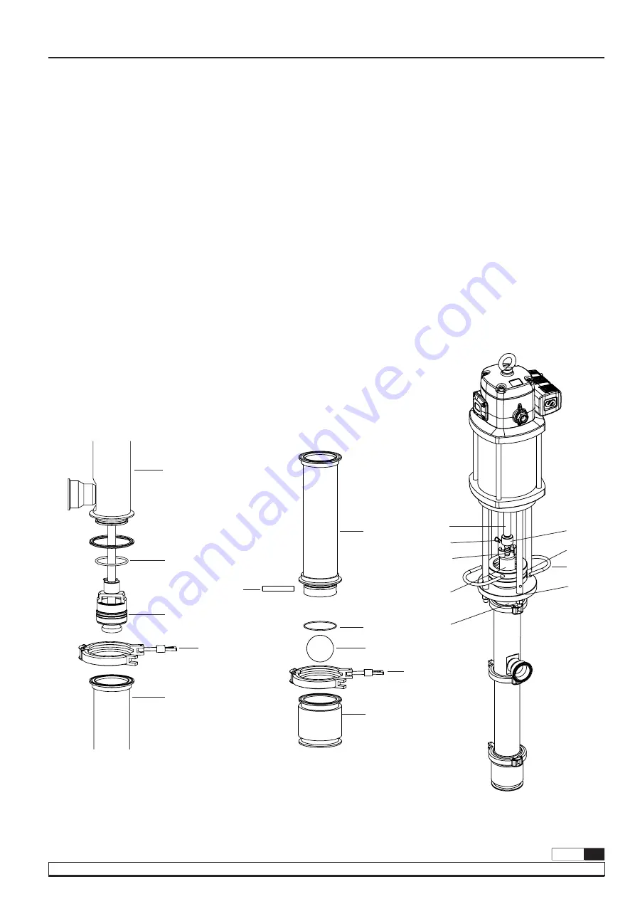
Fig. 19
Fig. 18
Fig. 20
79
82
86
89
90
78
89
91
92
93
51
77
78
74
76
69
68
70
4.
Fit the O-ring (82) and flat seal (77) onto outlet body (81). Push the
piston valve (88) assembly into the cylinder (89), you can use a soft
hammer to introduce gently the cylinder (89), them fit and tighten
the clamp ring (79) (fig. 18).
5.
Fit O-ring and valve (92) in inlet body (93). Introduce the retaining
pin (90) into the cylinder (89) and place the inlet body (93) into
cylinder (89). Then fit and tighten the clamp ring (78).
6.
The wet part is ready to assembly into the motor. Fit carefully the
gland nut (74) into the mounting flange (70). Place lock rings (69)
and push the springs (68) thought to fasten the assembly to pump
(fig. 20).
7.
The air motor piston rod (51) and the pump packing rod (81) should
now be pulled together so that they touch. Fit the two couplings
(80), one either side so that they fit into both the groove in the air
motor piston (51) and the groove in the pump packing rod (78).
Remove the spring clip (53) from the air motor piston rod (51) so
that the coupling cover (76) falls down to cover the couplings (77).
The spring clip (53) can now be refitted into the hole in the air
motor piston rod (51) to lock the assembly in place.
8.
Place the guards and reconnect the pump.
THE ORDER FOR ASSEMBLY IS AS FOLLOWS
81
53


