background image

LARIUS srl

Via Antonio Stoppani 21 - 23801 Calolziocorte (LC) ITALY

TEL. +39 0341 621152 - Fax +39 0341 621243 - larius@larius.com

www.larius.com

Summary of Contents for LARIUS SIRIO 60:1

Page 1: ...w w w l a r i u s c o m ED 04 11 2020 Manuale Cod 150170 SIRIO 60 1 Airless pneumatic pump for extrusion Code 99500 II 2G c IIB T6 OPERATING AND MAINTENANCE MANUAL EN...

Page 2: ...manual without prior notice This manual is to be considered as an English language translation of the original manual in Italian The manufacturer shall bear no responsibility for any damages or inconv...

Page 3: ...hieve the results desired quickly and professionally INDEX WARNINGS 2 WORKING PRINCIPLE 3 TECHNICAL DATA 4 DESCRIPTION OF THE EQUIPMENT 5 TRANSPORT AND UNPACKING 7 GUARANTEE CONDITIONS 7 SAFETY RULES...

Page 4: ...nt carry out the decompression procedure explained in this manual and prevent any risk of the equipment starting unexpectedly Report any risk of chemical reaction or explosion if this warning has not...

Page 5: ...of machines for coating and laminating Electrical and Electronics for component isolation Woodworking and plywood Cosmetic construction mechanics paper shipbuilding automobile industries Carpentry Ra...

Page 6: ...eed air pressurea 3 7 bar Maximum pressure of the product 420 bar Feed air inlet 3 4 BSPP Material exit 4 l min Maximum delivery 3 4 BSPP Weight 35 Kg Noise pressure level 80 dB A Dimensions A 1020 mm...

Page 7: ...ED 04 11 2020 Cod 150170 D Pos Description 1 Pump supply air input 2 Manometer reading air pressure alim pump 3 Feed air pressure regulator pump 4 Lubricant bucket 5 Material pumping group Pos Descrip...

Page 8: ...FLUIDO PORTATA MASSIMA R SIRIO 11 14 10 13 12 www larius com 6 SIRIO 60 1 ED 04 11 2020 Cod 150170 Pos Description 10 Pneumatic motor 11 Follower plate 12 Sound absorbing filter Pos Description 13 Ca...

Page 9: ...UT THE USE OF SAFETY DEVICES FOR THEIR OWN SAFETY AND ABOUTTHEGENERALRULESFORACCIDENTPREVENTION INCOMPLIANCEWITHINTERNATIONALREGULATIONSAND WITH THE LAWS OF THE COUNTRY WHERE THE PLANT IS USED THE BEH...

Page 10: ...SE Thehighspeedoftraveloftheproductinthehose can create static electricity through discharges andsparks Itissuggestedtoearththeequipment The pump is earthed through the earth cable of the supply The g...

Page 11: ...difficult suction of the pump slowly open the bleeder valve and close it when some material comes out SETTING UP PUMP FASTENING ON THE RAM For the correct fastening of the pump on the ram use the hole...

Page 12: ...he product To tighten the packing nut L1 use wrench supplied L2 The packing nut must be tightened so as to avoid wastes of product but not excessively to avoid the seizure of the pumping piston and th...

Page 13: ...1 ED 04 11 2020 Cod 150170 M Always close the compressed air supply and release the pressure in the plant beforecarrying out the disassembly of the pumping group In case the product being used is toxi...

Page 14: ...mping group 3a from the motor 3b Necessary tools and equipment Procedure 2 1 Disconnect the components 2a of the pump 2b Necessary tools and equipment 3 3b 3a 2a 2b www larius com 12 SIRIO 60 1 ED 04...

Page 15: ...nt Necessary tools and equipment Procedure 4 1 Unscrew the three nuts 4a 4b and 4c using a wrench 4d 4 Procedure 5 1 Slide the complete pumping group 4d 4a 4b 4c www larius com 13 SIRIO 60 1 ED 04 11...

Page 16: ...mponent 6a 6 2 Slide off the component 6b 6 3 Loosen the ring nut 6c with pin 6d 6 4 Unscrew and remove the ring nut 6e Necessary tools and equipment 6 6a 6b 6d 6e 6c www larius com 14 SIRIO 60 1 ED 0...

Page 17: ...8c 7 Necessary tools and equipment Procedure 7 1 Push downwards the motor piston rod 7a till the shovel plate comes out of the housing 7b 7b 8 Necessary tools and equipment 8c 8b 8a 7a www larius com...

Page 18: ...screw the component 10c and remo ve the copper rings 10d Necessary tools and equipment Procedure 9 1 Unscrew the cylinder 9a remove the washer 9b and the shutter housing 9c 9a 9c 9b 10 10b 10a 10d 10c...

Page 19: ...Necessary tools and equipment 11 CLEANER Direction of assembly A B C B C B D E A Female STEEL ring cod 96984 B White gasket cod 96982 1 C Black gasket cod 96982 D Male STEEL ring cod 96983 E Gasket h...

Page 20: ...ce it with the new spare parts 12a Necessary tools and equipment 13 Procedure 13 1 Unscrew the component 13a and slide the rod 13b Necessary tools and equipment CLEANER 13a 13b 13b INFERIOR SEALS 12a...

Page 21: ...ecomponent 14a andslide the rod 14 2Clean and lubricate the gasket housing and replace it with the new spare parts 14b Necessary tools and equipment 14 CLEANER 14a 14b PTFE Polietilene www larius com...

Page 22: ...e it if necessary 15 3 Clean and lubricate the threaded area and reassemble the component Necessary tools and equipment 16 Procedure 16 1 Insert the component 16a and screw with the wrench Necessary t...

Page 23: ...a and screw the rod 17 2 Insert the copper rings reassemble the component 17b andinserttherod 17c 17 3 Screw the component 17d Necessary tools and equipment 17a 17 17b 17c 17d www larius com 21 SIRIO...

Page 24: ...ut 19b with the pin 19c Procedure 18 1 Reassemble the washer and the shutter housing and screw the cylinder 18a 18 2 Reassemble shovel plate 18b and insert the motor piston Necessary tools and equipme...

Page 25: ...and and screw with the wrench Necessary tools and equipment Procedure 20 1 Insert the complete pumping group 21a 20 2 Screw the three nuts using two wrench Necessary tools and equipment 20a 20b 21 21a...

Page 26: ...t Procedure 22 1 Connect the pumping group 22a to motor 22b Procedure 23 1 Connect the component 23a to pump 23b Necessary tools and equipment 22 22b 22a 23a 23b www larius com 24 SIRIO 60 1 ED 04 11...

Page 27: ...again a blocked motor close the air supply and release pressure in the plant This operation should allow the recovery of the valves In case the motor is blocked proceed as follows Close the air supply...

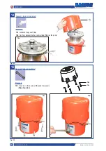
Page 28: ...motor cap 1a and pull it upwards together with the guide rod 1b 1e 1 3 Hold the guide rod 1b and remove the plug 1a using two wrenches Necessary tools and equipment 1a 1b 1a 1b 1c 1a 1b 1c 1c 1d 1c 1e...

Page 29: ...s and equipment Procedure 2 1 Remove the screws 2a and the washers 2b 2c 2d Procedure 3 1Carefullyextractthemotorcylinder 3a fomthepump 2b 2a 2c 2d 3a www larius com 27 SIRIO 60 1 ED 04 11 2020 Cod 15...

Page 30: ...assemble the cap 4b Procedure 5 1 Press at the point 5a to snap inside the rocker arm stud screw Procedure 6 1 Unscrew and remove the two screws 6a 6b with 2 13mm wrenches as shown in figure 6c Necess...

Page 31: ...over the cap to accompany it 7b Necessary tools and equipment Procedure 8 1 Remove the two valve screws 8a 8b Necessary tools and equipment Procedure 9 1 Proceed with disassembly and replace the 6 se...

Page 32: ...l v e s c r e w s 12a as shown in the drawing Necessary tools and equipment Necessary tools and equipment Procedure 11 1 Remove the OR gasket 11a and replace it if necessary with a spare part 10a 10b...

Page 33: ...screw as shown in the drawing keeping a tolerance distance of 3 5 mm crosspiece valve screw Necessary tools and equipment Procedure 13 1 Unscrew the cap 13a holding the guide rod with a 7mm wrench The...

Page 34: ...eassemble the motor cylinder 14b on the pump Necessary tools and equipment Necessary tools and equipment Procedure 15 1 Re screw in the 6 screws 15a and the washers 15b 15c 15d 14a 15c 15d 15b 15a www...

Page 35: ...cylinder 16d 16 2 Remove the nut 16c 16 3 Re screw the cap 16a onto the rod using 2 wrenches and re screw in the cap on the cover 16e Necessary tools and equipment 16c 16a 16b 16a 16b 16c 16c 16d 16c...

Page 36: ...le suction tube Gaskets of the pumping rod worn Replace the lower gaskets Suction valve worn or partially clogged Disassemble the suction valve Clean and or replace if possible the parts worn Suction...

Page 37: ...SPARE PARTS Complete pneumatic motor pag 36 Pneumatic regulator pag 37 Complete pump pag 38 www larius com 35 SIRIO 60 1 ED 04 11 2020 Cod 150170 Q R S...

Page 38: ...2 9 10 NON COMPRESA NELL ASSIEME MOTORE 11 12 8 40 39 MADE IN ITALY RAPPORTO RATIO MASSIMA PRESSIONE FLUIDO PORTATA MASSIMA R SIRIO WARNING always indicate code and quantity for each part required CO...

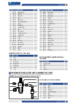
Page 39: ...1 Pos Code Description Q ty 21 99057 Valve screw 2 22 99058 Valve gasket 2 23 96011 Guide spring 2 24 96025 Screw Tce 2 25 99059 O ring 1 26 96009 Seal bushing 6 27 99061 Exchange spring 2 28 99060 R...

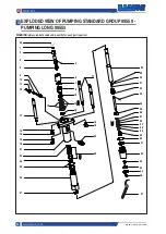
Page 40: ...18 19 34 36 28 30 25 42 43 44 45 46 47 29 41 37 37 38 39 31 32 33 35 38 40 18 20 23 19 EXPLODED VIEW OF PUMPING STANDARD GROUP 99550 PUMPING LONG 99553 WARNING always indicate code and quantity for ea...

Page 41: ...n Q ty 24 96878 Female ring for middle gaskets 1 25 96883 Copper gaskets 3 26 96897 Housing for lower gaskets 1 27 96889 Seal 1 28 96988 Piston rod 1 29 96880 Ball clamp pin 1 30 96879 Ball guide 1 31...

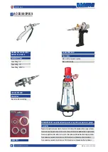
Page 42: ...NEUMATIC HOIST complete with compressed air regulators and pressure gauges Description Pneumatic hoist for drums from 30 to max 200 litres with double effect single cylinder Pneumatic hoist for drums...

Page 43: ...series Ghibli 24 1 EXTRUSION REGULATORS KIT Description Low pressure flow regulator Low pressure flow regulator for dense products Regulator kit for high pressure recirculation Rif 7000 NOZZLES EXT 85...

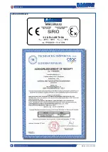
Page 44: ...ATEX CERTIFICATE www larius com 42 SIRIO 60 1 ED 04 11 2020 Cod 150170...

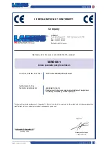
Page 45: ...ility that the product Company Signature Calolziocorte 18 September 2020 Location Date complies with the directives EC Directive 2006 42 Machinery Directive furthermore to the harmonized standards UNI...

Page 46: ...LARIUS srl Via Antonio Stoppani 21 23801 Calolziocorte LC ITALY TEL 39 0341 621152 Fax 39 0341 621243 larius larius com www larius com...

Reviews: