background image

3

R. 09/23 855 878

 SAMOA Industrial, S.A. · Pol. Ind. Porceyo,  I-14 · Camino del Fontán, 831 · 33392 - Gijón - Spain · Tel.: +34 985 381 488 · www.samoaindustrial.com

2023_09_15-11:30

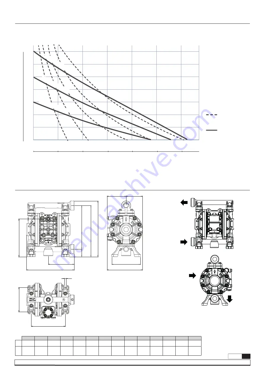
DIMENSIONS

CAPACITY CURVE

A

B

C

D

E

F

G

H

I

J

K

L

M

N

mm

202

110

161

237

217

32

185

151

122

81

70

145

104

8

in

7.95”

4.33”

6.34”

9.33”

8.54”

1.26”

7.28”

5.95”

4.80”

3.19”

2.76”

5.71”

4.09”

0.32”

DIMENSIONS

FLUID OUTLET

(3/8” BSP-F/NPT-F)

FLUID INLET

(3/8” BSP-F/NPT-F)

AIR INLET

(1/4” NPSM-F)

AIR EXHAUST

0  5  10 15 20  25 30

1,5 3 4,5 7,5 10,5

6

5

4

3

2

1

0

bar psi

101

87

72

58

43

30

15

0

SCFM

Nm

3

/h

1 2 3 4,5 6,5

0 1.3  2.6 3.9 5.2  6.6  8

l/min

US gal/min

7 bar (101 psi)

5 bar (72 psi)

3 bar (43 psi)

Air consumption

Fluid pressure

*Tested at room temperature, using water. Flooded pump with positive suction head.

Pump flow

AIR CONSUMPTION 

PUMP FLOW 

A

D

C

B

E

F

G

J

I

H

K

N

L

M

Summary of Contents for UP03B Series

Page 1: ...d technical service guide Gu a de servicio t cnico y recambios Guide d instructions et pi ces de rechange Service und Ersatzteilhandbuch 3 8 DOUBLE DIAPHRAGM PLASTIC PUMP UP03 31 l min 8 2 gal min 2 B...

Page 2: ...Buna N Two piece Z PTFE Teflon with Santoprene backer TECHNICAL DATA PUMP NOMENCLATURE UP03B XXX XXX PUMP NOMENCLATURE EN UP03 RATIO 1 1 MAXIMUM FREE FLOW 31 l min 8 2 Us gal min DELIVERY PER CYCLE 0...

Page 3: ...8 5 95 4 80 3 19 2 76 5 71 4 09 0 32 DIMENSIONS FLUID OUTLET 3 8 BSP F NPT F FLUID INLET 3 8 BSP F NPT F AIR INLET 1 4 NPSM F AIR EXHAUST 0 5 10 15 20 25 30 1 5 3 4 5 7 5 10 5 7 6 5 4 3 2 1 0 bar psi...

Page 4: ...using this equipment are trained on the operation the product and its limitations Use safety equipment as required Do not use a model with aluminium wetted parts to pump fluids for human consumption...

Page 5: ...its place use brackets to secure its base Fasten all bolts with the torques contained in this manual REPAIR AND MAINTENANCE section Let the pump running for a whole day After that check the torques a...

Page 6: ...is manual before operating the pump If the symbol Ex is in the pump nameplate it can be used in the potentially explosive atmospheres indicated areas details on the ATEX manual WARNING If the pump ope...

Page 7: ...uce the inlet valve flow to adjust the pressure and fluid volume Securely fix the pump with the bracket to the base Ice formation in the air exhaust Remove ice from the air bypass valve and check and...

Page 8: ...hragms Once the fluid covers are removed proceed as follows 1 Remove the two screws 27 that secure the air sensor to the top 2 Remove all sensor components 22 23 24 25 26 Clean the area 3 Insert new c...

Page 9: ...gently pulling back 4 Remove the used diaphragm In case of two piece diaphragms diaphragm with outer piston use an adjustable wrench and apply corresponding torque 5 Repeat for opposite side IMPORTAN...

Page 10: ...3 m 10 dry 7 m 23 wet PESO PP 1 8 Kg 4 lb PP Conductivo 2 Kg 4 4 lb PVDF 2 3 Kg 5 1 lb Acetal Conductivo 2 1 Kg 4 6 lb CONEXIONES DE ENTRADA SALIDA DE FLUIDO 3 8 BSP F Roscada 3 8 NPT F Roscada ENTRAD...

Page 11: ...8 5 95 4 80 3 19 2 76 5 71 4 09 0 32 DIMENSIONES SALIDA FLUIDO 3 8 BSP F NPT F ENTRADA FLUIDO 3 8 BSP F NPT F ENTRADA AIRE 1 4 NPSM F ESCAPE DE AIRE 0 5 10 15 20 25 30 1 5 3 4 5 7 5 10 5 7 6 5 4 3 2 1...

Page 12: ...uipo est n formados sobre el funcionamiento el producto y sus limitaciones Utilizar el equipo de seguridad necesario No utilice un modelo con partes h medas de aluminio para bombear fluidos para el co...

Page 13: ...re Apriete todos los tornillos con el par recomendado en este manual secci n de REPARACI N Y MANTENIMIENTO Deje la bomba funcionando durante un d a entero Al d a siguiente compruebe los pares de aprie...

Page 14: ...as de atm sferas potencialmente explosivas detalles en el manual ATEX ADVERTENCIA si la bomba opera sin conexi n a tierra o con una conexi n incorrecta la fricci n entre las piezas y la abrasi n del f...

Page 15: ...uraci n de la tuber a del lado de succi n Se produce cavitaci n Ajuste la presi n de suministro de aire y la presi n de descarga Reduzca la altura de aspiraci n Se producen vibraciones Ajuste la presi...

Page 16: ...PE DE AIRE 1 Afloje los cuatro tornillos del distribuidor y retire el conjunto 2 Retire los 2 tornillos inferiores y el cuerpo del escape si fuera necesario sustituirlo 3 Coloque el nuevo escape en el...

Page 17: ...tirando con la mano En caso de diafragma con pist n exterior dos piezas usar una llave ajustable y aplique el par correspondiente 5 Repita en el lado opuesto IMPORTANTE Aproxime progresivamente los t...

Page 18: ...ON MAXIMALE 3 m 10 dry 7 m 23 wet POIDS PP 1 8 Kg 4 lb PP Conductif 2 Kg 4 4 lb PVDF 2 3 Kg 5 1 lb Acetal Conductif 2 1 Kg 4 6 lb RACCORDS D ENTR E ET DE SORTIE DU FLUIDE 3 8 BSP F Filet e 3 8 NPT F F...

Page 19: ...3 19 2 76 5 71 4 09 0 32 DIMENSIONS SORTIE FLUIDE 3 8 BSP F NPT F ENTR E DU FLUIDE 3 8 BSP F NPT F ENTR E D AIR 1 4 NPSM F CHAPPEMENT D AIR 0 5 10 15 20 25 30 1 5 3 4 5 7 5 10 5 7 6 5 4 3 2 1 0 bar p...

Page 20: ...u fonctionnement au produit et ses limites Utilisez les quipements de s curit n cessaires N utilisez pas un mod le avec des pi ces en contact avec le fluide en aluminium pour pomper des fluides destin...

Page 21: ...ns d ancrage Serrez tous les boulons au couple recommand dans ce manuel secci n de REPARACI N Y MANTENIMIENTO Laissez la pompe fonctionner pendant une journ e enti re Ensuite v rifiez nouveau les coup...

Page 22: ...dansleszonesindiqu esd atmosph respotentiellement explosives d tails dans le manuel ATEX AVERTISSEMENT Si la pompe est utilis e sans mise la terre ou de mani re incorrecte la friction entre les pi ces...

Page 23: ...tion La pompe vibre R gler la pression d air et la pression de refoulement R duire le d bit de la vanne d entr e pour r gler la pression et le volume de fluide Fixez solidement la pompe avec le suppor...

Page 24: ...distributeur et retirer l ensemble 2 D poser les 2 vis inf rieures et le corps d chappement s il doit tre remplac 3 Monter le nouvel chappement sur le nouveau distributeur 4 Boulonner le collecteur d...

Page 25: ...rieur deux pi ces utilisez une cl molette et appliquer le couple correspondant 5 R p tez de l autre c t IMPORTANT Rapprocher progressivement les vis du couvercle avant de les serrer d finitivement IM...

Page 26: ...ITCH Polypropylen 1 8 Kg 4 lb Leitf higes Polypropylen 2 Kg 4 4 lb PVDF 2 3 Kg 5 1 lb Leitf higes Acetal 2 1 Kg 4 6 lb FLUIDEINLASS EINZELEINLASS FLUIDAUSLASS 3 8 BSP F Gewindeverbindung 3 8 NPT F Gew...

Page 27: ...4 80 3 19 2 76 5 71 4 09 0 32 ABMESSUNGEN FL SSIGKEITSAUSGANG 3 8 BSP F NPT F FL SSIGKEITSEINGANG 3 8 BSP F NPT F LUFT EINGANG 1 4 NPSM F LUFT AUSLASS 0 5 10 15 20 25 30 1 5 3 4 5 7 5 10 5 7 6 5 4 3...

Page 28: ...verwenden in der Bedienung dem Produkt und seinen Grenzen geschult sind Verwenden Sie die erforderliche Sicherheitsausr stung Verwenden Sie ein Modell mit aluminiumber hrten Teilen nicht zum Pumpen v...

Page 29: ...ie Pumpe mit den Zugbolzen Ziehen Sie alle Schrauben mit dem in dieser Anleitung empfohlenen Drehmoment an Lassen Sie die Pumpe einen ganzen Tag lang laufen Pr fen Sie danach die Drehmomente erneut En...

Page 30: ...eingesetzt werden Details im ATEX Handbuch WARNUNG Wenn die Pumpe ungeerdet oder unsachgem geerdet betrieben wird kann durch Reibung zwischen den Teilen und Abrieb durch die Fl ssigkeit statische Ele...

Page 31: ...nd berpr fen Sie die Konfiguration der Saugrohrleitung Die Pumpe vibriert Stellen Sie den Lufteingangs und Luftausgangsdruck nach Reduzieren Sie den Strom am Einlassventil um den Druck und das F rderv...

Page 32: ...das Auspuffgeh use entfernen falls es ersetzt werden muss 3 Den neuen Auspuff an den neuen Verteiler montieren 4 Schrauben Sie den Luftverteiler mit einem Drehmoment von 2 N m 1 5 ft lbs am Pumpengeh...

Page 33: ...pritzten Membranen durch Ziehen von Hand abschrauben bei Membranen mit Au enkolben zweiteilig einen verstellbaren Schraubenschl ssel verwenden und das entsprechende Drehmoment aufbringen 5 Wiederholen...

Page 34: ...HP 2XX Kit N kit N UP03R WP 00X UP03R AM 200 Kit N UP03R WP 00Z Kit N UP03R HP 5B0 Part N Part N UP03R HP 6B0 UP03R HP 7X0 Part N Part N UP03R HP 3X0 16 17 18 17 15 17 18 16 1 2 3 4 5 6 7 8 9 10 11 12...

Page 35: ...backer A Diaphragm leak detectors B Diaphragm leak detectors ATEX C Stroke sensor D Stroke sensor PLC E Stroke sensor ATEX F Diaphragm leak detectors Stroke sensor G Diaphragm leak detectors Stroke s...

Page 36: ...R HP 2WB UP03R HP 2WN 15 B Conductive PP UP03R HP 2BB UP03R HP 2BN 15 D Conductive Acetal UP03R HP 2DB UP03R HP 2DN 15 4 FLUID COVER TAPA DE FLUIDO COUVERCLE DE FLUIDE FL SSIGKEITSDECKEL KIT Pos P Pol...

Page 37: ...RECHANGE TEILELISTE UP0302 B 6 PTFE O RINGS JUNTAS T RICAS JOINTS TORIQUES O RINGEN KIT Pos 999 PTFE O rings UP03R WP 999 10x 17 7 BALLS BOLAS BOULES B LLES KIT Pos C Acetal UP03R WP 0C0 4x 16 T PTFE...

Page 38: ...855 878 R 09 23 SAMOA Industrial S A Pol Ind Porceyo I 14 Camino del Font n 831 33392 Gij n Spain Tel 34 985 381 488 www samoaindustrial com 2023_09_15 11 30 EN EN ES FR DE NOTES NOTAS NOTES ANMERKUNG...

Page 39: ...9 R 09 23 855 878 SAMOA Industrial S A Pol Ind Porceyo I 14 Camino del Font n 831 33392 Gij n Spain Tel 34 985 381 488 www samoaindustrial com 2023_09_15 11 30 EN ES FR DE NOTES NOTAS NOTES ANMERKUNGE...

Page 40: ...Font n 831 33392 Gij n Espa a declara que el los producto s UP03B XXX XXX cumple n con la s Directiva s de la Uni n Europea 2006 42 CE ES SAMOA INDUSTRIAL S A Pol Ind Porceyo I 14 Camino del Font n 8...

Reviews: