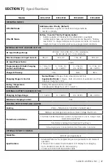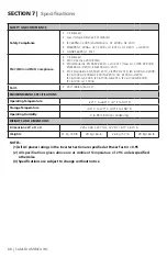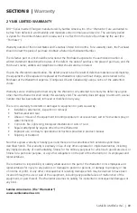
10 | SAMLEX AMERICA INC.
SAMLEX AMERICA INC. | 11
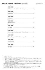
APPENDIX A
SECtION 4 |
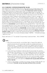
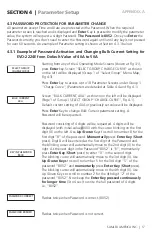
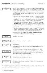
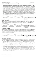
Parameter Setup
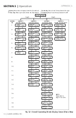
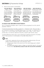
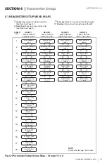
noteS FoR FiG 3.2:
1. • The 3-digit No. XXX in “RC-XXX” indicates the Firmware Revision No. for the Remote
Control EVO-RC
• The 4-digit No. XX.X in EVO-VX.XX denotes the Firmware Revision No. for the EVO
TM
Inverter/Charger
• The 4-digit No. XXXX in EVO-XXXX denotes the Model No. of Evolution
TM
Series
Inverter/Charger i.e. EVO-2212 / 2224 / 3012 / 4024
2. The 3 or 4-digit abbreviations on the top right corner of the 19 Screens (Screen Nos. 1 to 19)
under “CHARGING” Mode (Column 4, Group 3) will indicate one of the following 6 charg-
ing states:
Abbreviation
normal (n)
3 Stage Charging
equalization
(e) 4-Stage Charging
N-CC
Constant Current (CC),
Bulk Stage
–
N-CV
Constant Voltage (CV),
Absorption Stage
–
E-CC
–
Constant Current (CC),
Bulk Stage
E-CVA
–
Constant Voltage Absorption
(CVA) Stage
E-CVE
–
Constant Voltage Equalization
(CVE) Stage
FLOAT
Float Stage
Float Stage
19 Screens (Screen Nos. 1 to 19) for “CHARGING” Mode (Column 4, Group 3) are shown
as an example for Bulk Charging Stage in Normal Charging Mode (N-CC). Depending
upon the Charging Mode and Stage the unit is in at any particular time, 19 sets of screens
will be seen for each of the 6 states of operation in Charging Mode: N-CC, N-CV, E-CC,
E-CVA, E-CVE or Float
3. Screen Up is shown with downward pointer
because Screen Nos. in this Menu Map
increase in the downward direction
4. Screen Down is shown with upward pointer
because Screen Nos. in this Parameter Setting
Menu Map decrease in the upward direction

