24 | SAMLEX AMERICA INC.
APPENDIX A
SECtION 4 |
Parameter Setup
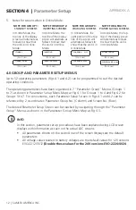
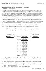
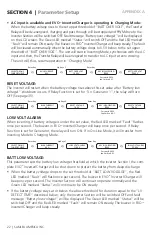
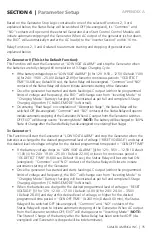
CHARGe MoDe:
Default setting is 3-Stage "Normal Mode" (Parameter Screen setting shows "0=Normal"). The
mode can be changed at any time to 4-stage "Equalization Mode" (Change Screen setting to
"1=Equalize"). After "Equalization Mode" is completed (the charger enters Float Stage after
completing Equalization Stage), the screen automatically resets to Normal (0= Normal).
SELECT GROUP
CHARGE CURVE
BULK CURRENT
40 A
CHARGE MODE
0=Normal
Enter Key
ò
Up Key x 11
ò
CHARGE MODE
0=Normal
ò
KEY IN PASSWORD
0000
Enter Key
ò
Password 8052
See Section 4.3.1
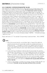
onLine MoDe:
Please refer to Section 4.8.5 of the attached Owner's Manual for Evolution
TM
Series Inverter/
Charger for general description and applications for Offline and Online Modes.
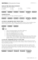
The default factory setting for this unit is the Offline Mode (ONLINE MODE, 0 = Off). Pro-
gramming steps are shown below to charge from (i) the default setting of Offline Mode
(ONLINE MODE, 0 = Off) to Online Mode (ONLINE MODE, 1 = On) or (ii) to change back from
Online Mode (ONLINE MODE, 1 = On) to Offline Mode (ONLINE MODE, 0 = Off).
SELECT GROUP
CHARGE CURVE
BULK CURRENT
40A
ONLINE MODE
0=Off
Enter Key
ò
Up Key x 12
ò
ONLINE MODE
0=Off
ò
KEY IN PASSWORD
0000
Enter Key
ò
Password 8052
See Section 4.3.1
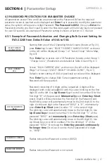
onLine oPtion:
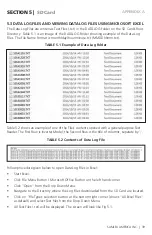
This setting is effective only when Online Mode is selected (ONLINE MODE, 1=On) as per sub-
section titled "ONLINE MODE" above. The default setting is: 0=Option 1. Programming steps
are given below:
SELECT GROUP
CHARGE CURVE
BULK CURRENT
40A
ONLINE OPTION
0=Option 1
Enter Key
ò
Up Key x 13
ò
ONLINE OPTION
0=Option 1
ò
KEY IN PASSWORD
0000
Enter Key
ò
Password 8052
See Section 4.3.1
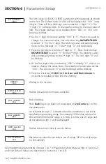
Details of the two options are given below:
0= Option 1 (Default):
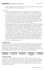
• The Transfer Relay will be switched ON (energized) if the battery voltage drops to
“LOW VOLT ALARM” [(i) for 12V: 9.5V – 12.5V / Default 11.0V (ii) for 24V: 19.0V –
25.0V / Default 22.0V] or lower for sustained period = “GS DETECT TIME” (0-600 sec;
Default 10 sec). The EVO
TM
will change over to “Charging Mode” and qualified AC
input from the Grid will be passed through to the AC Output and at the same time,
the Internal AC Charger will start charging the battery. If an external Solar Charge
Controller is also connected to the External Charging Terminals (3 and 4, Fig 2.1 in
Owner's Manual for Evolution
TM
Series Inverter/Charger), the internal AC Charger will
limit the charging current to a value = (Programmed Value of Bulk Current – Value of
Current fed from the external Solar Charge Controller).
• Charging will take place as per full and complete 3-Stage Charging Algorithm
(“CHARGE MODE” 0=Normal).
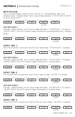
• Transfer Relay will be switched OFF (de-energized) on entering “Float Stage” on
completion of “Absorption Stage” and the unit will change over to “Inverting Mode”

