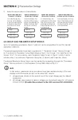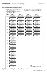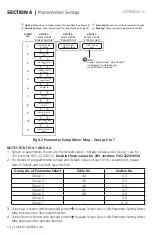
24 | SAMLEX AMERICA INC.
SAMLEX AMERICA INC. | 25
APPENDIX A
SECtION 4 |
Parameter Setup
(NOTE: The battery will be charged to 100% State of Charge after the Transfer Relay
has de-energized on entering Float Stage)
1= Option 2:
• The Transfer Relay will be switched ON (energized) if the battery voltage drops to
“LOW VOLT ALARM” [(i) for 12V: 9.5V – 12.5V / Default 11.0V (ii) for 24V: 19.0V
– 25.0V / Default 22.0V], or lower for sustained period = “GS DETECT TIME” (0-600
sec; Default 10 sec). The EVO
TM
will change over to “Charging Mode” and qualified
AC input from the Grid will be passed through to the AC Output and at the same
time, the Internal AC Charger will start charging the battery. If an external Solar
Charge Controller is also connected to the External Charging Terminals (3 and 4, Fig
2.1 in Owner's Manual for Evolution
TM
Series Inverter/Charger), the internal AC Char-
ger will limit the charging current to a value = (Programmed Value of Bulk Current –
Value of Current fed from the external Solar Charge Controller).
• Charging will proceed as per 3-Stage Charging Algorithm (CHARGE MODE 0=Normal)
• The Transfer Relay will be switched OFF (de-energized) after the programmed value of
“GEN OFF TIME” (0 to 240 min; Default 60 min) counted from the time the battery
voltage rises to the programmed value of “RESET VOLTAGE” [(i) for 12V: 12.0V –
17.0V / Default 14.0V (ii) for 24V: 24.0V – 35.0V / Default 28.0V]. The unit will exit
“Charging Mode” and revert to “Inverting” Mode. [NOTE: It is likely that (i) the bat-
tery voltage may rise higher than the programmed value of “RESET VOLTAGE” up to
the programmed value of Absorption Voltage (If the programmed value of absorption
Voltage is > the “RESET VOLTAGE”) due to continuation of charging for the pro-
grammed value of “GEN OFF TIME” after the voltage has reached the programmed
value of “RESET VOLTAGE” and (ii) the battery may not be charged fully after the
Transfer Relay has de-energized because the programmed values of “RESET VOLT-
AGE” and “GEN OFF TIME” may not match the desired Absorption Voltage / Absorp-
tion Time of the battery being used.]
FLoAtinG eXit:
Please refer to Sections 5.6.4 and 5.8 of the Owner's Manual for Evolution
TM
Series Inverter/
Chargers regarding automatic resetting of 3 and 4 Stage Charging Cycles respectively. When
charging is in Float Stage and the battery discharges to the programmed discharged volt-
age level, the Charging Cycle is reset to the Bulk Stage of the 3 Stage Charging Profile. The
programmable range of this voltage level is 10 to 13V for 12V battery and 20 to 26V for 24V
battery and the Default Setting is 12V for 12V battery and 24V for 24V battery.
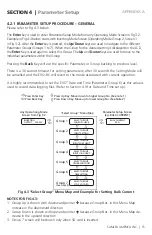
SELECT GROUP
CHARGE CURVE
BULK CURRENT
40A
FLOATING EXIT
12.00V
Enter Key
ò
Up Key x 14
ò
FLOATING EXIT
12.00V
ò
KEY IN PASSWORD
0000
Enter Key
ò
Password 8052
See Section 4.3.1
GS DeteCt tiMe
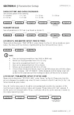
This parameter is a Programmable Timer (0-600sec; Default: 10 sec) that is used for pro-
gramming On-Line / Off Line UPS Modes (Section 4.4) and Automatic Starting and Stopping
of Generator (Section 4.8 under “Relay Function”). The Timer sets the duration the battery
voltage has to remain at threshold of “LOW VOLT ALARM” condition [(i) for 12V: 9.5V –
12.5V / Default 11.0V (ii) for 24V: 19.0V – 25.0V / Default 22.0V], or lower before the fol-
lowing actions are initiated:


