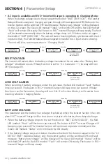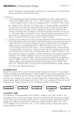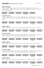
32 | SAMLEX AMERICA INC.
SAMLEX AMERICA INC. | 33
APPENDIX A
!
Attention!
Logique On / Off montré dans la figure 4,8 contrôle également le fonctionnement du bouton ON/OFF sur le panneau
d’avant de l’onduleur chargeur de l' EVO
TM
(11 , figure 2,1 dans le manuel d'EVO
TM
onduleur chargeur propriétaire ) . Le
réglage par défaut est « Button Type ».
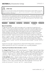
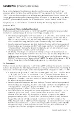
If the On/Off control is changed to external "Remote Switch", it will not be possible to switch
On/Off the EVO
TM
Inverter/Charger from the front panel On/Off Push Button because it will
work with Switch Type Logic at Fig 4.8: it will be ON only as long as the Push Button is kept
pressed and will switch off when released.
SELECT GROUP
CHARGE CURVE
SELECT GROUP
OTHER FUNCTION
REMOTE SWITCH
0 = Button
POWER SAVING
1 = Enable
Up Key x 4
ò
Enter Key
ò
Up Key x 3
ò
REMOTE SWITCH
0 = Button
ò
KEY IN PASSWORD
0000
Enter Key
ò
Password 8052
See Section 4.3.1
ReLAY FUnCtion:
A Single Pole Double Throw (SPDT) Status Relay with 3 contacts has (Contact Rating: 3A ;
125 VAC / 30 VDC) been provided in the Evolution
TM
Series (EVO
TM
) Inverter/Chargers that can
be used for (i) signaling of operational status (Functions 0 and 1) and (ii) providing contact
closure / opening for automatic starting and stopping of generator through appropriate
optional Generator Auto Start / Stop Control Module (Functions 2, 3 and 4). The 3 contacts
of the Status Relay are connected to 3 terminals of Terminal Block (14, Fig 2.1 in Owner's
Manual for Evolution
TM
Series) on the front panel. The contacts are marked “NO” (Normally
Open), “Common” and “NC” (Normally Closed). When the Status Relay is OFF (de-energized),
contacts marked “Common” and “NO” will be in open condition and contacts marked
“Common” and “NC” will be in closed condition. When the Status Relay is ON (energized),
contacts marked “Common” and “NO” will close and contacts marked “Common” and “NC”
will open.
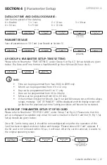
Diagram showing steps for programming the RELAY FUNCTION parameter and details of 5
different associated Functions 0 to 4 are provided in the succeeding paragraphs
Signaling of operational States (Functions 0 and 1)
0 = Charger/other:
When the EVO
TM
Inverter/Charger is in “Charging” Mode, the Status Relay
will be OFF (de-energized) [(i) “Common” and “NO” contacts will be in open condition and (ii)
“Common” and “NC” contacts will be in closed condition]. In “Other” operating modes i.e. in
“Inverting”, “Power Save” or in “Standby” Modes, the Status Relay will be ON (energized) [(i)
Common and “NO” contacts will close and (ii) “Common” and “NC” contacts will open]
1= normal/Fault:
When in “Normal” operational state i.e. when not in Fault Mode, the Status
Relay will be OFF (de-energized) [(i) “Common” and “NO” contacts will be in open condition
and (ii) “Common” and “NC” contacts will be in closed condition]. When the EVO
TM
Inverter/
Charger is in “Fault” mode, the Status Relay will be ON (energized) [(i) Common and “NO”
contacts will close and (ii) “Common” and “NC” contacts will open].
SECtION 4 |
Parameter Setup


