34 | SAMLEX AMERICA INC.
APPENDIX A
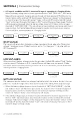
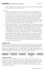
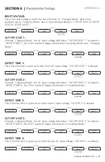
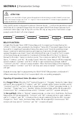
Automatic Starting and Stopping of Generator (Functions 2, 3 and 4)
i
inFo
The following programmable parameters have been referred to in the description be-
low. Links to detailed information on these parameters are given below:
• “LOW VOLT ALARM”: Please refer to Screen 8 of Group 1 of Parameter Setup
Menu Map at Fig 4.1, Table 4.4 and Section 4.4
• “GS DETECT TIME”: Please refer to Screen 16 of Group 1 of Parameter Setup Menu
Map at Fig 4.1, Table 4.4 and Section 4.4
• “CHARGE MODE”: Please refer to Screen 12 of Group 1 of Parameter Setup Menu
Map at Fig 4.1, Table 4.4 and Section 4.4
• “GEN ON TIME”: Please refer to Screen 17 of Group 1 of Parameter Setup Menu
Map at Fig 4.1, Table 4.4 and Section 4.4
• “GEN OFF TIME”: Please refer to Screen 18 of Group 1 of Parameter Setup Menu
Map at Fig 4.1, Table 4.4 and Section 4.4
• “RESET VOLTAGE”: Please refer to Screen 7 of Group 1 of Parameter Setup Menu
Map at Fig 4.1, Table 4.4 and Section 4.4
The Normally Open “NO” and “Common” contacts of Status Relay (14, Fig 2.1 in the Owner's
Manual for Evolution
TM
Series Inverter/Charger) can be used to also automatically start and
stop generator through appropriate external Generator Auto Start / Stop Module. 3 options
(Functions 2, 3 and 4) explained below are available for carrying out this function depending
upon user requirements. The “Common” and “NO” terminals are wired to the optional
Generator Auto Start / Stop Control Module which, in turn, is wired to the Remote Start / Stop
connections on the Generator. The AC output terminals of the Generator are wired to the
Generator Input Terminals on the EVO
TM
(7, 8, 9 in Fig 2.3 in Owner's Manual for EVO
TM
Series
Inverter/Charger). For installation details, please refer to Section 3.15 / Fig 3.13 and Section
3.16 / Fig 3.14 in the Owner's Manual for EVO
TM
Series Inverter/Charger.
i
inFo
It is recommended that “GSCM-Mini” Series of Generator Start / Stop Control Module,
appropriate for the generator to be used, may ordered directly from
Atkinson Electronics www.atkinsonelectronics.com
Based on the Generator Start Logic contained in of one of the selected Functions 2, 3 or
4 explained below, the Status Relay will be switched ON (energized), its “Common” and
“NO” contacts will close and the external Generator Start / Stop Control Module will initiate
automatic starting of the Generator. Once the Generator has started and starts feeding AC
output to EVO
TM
(within the programmed limits of voltage and frequency), the EVO
TM
will be
synchronized with the Generator and once synchronization is completed, the load will be
transferred instantly (within 1 ms) to the Generator at Zero Crossing of the voltage waveform
for seamless transfer and for better protection of Transfer Relay contacts. The EVO
TM
will now
operate in “Charging Mode” with the AC power from the Generator charging the batteries as
well as providing power to the AC load(s).
SECtION 4 |
Parameter Setup


