36 | SAMLEX AMErICA INC.
SAMLEX AMErICA INC. | 37
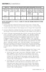
tAbLe 3.1 SiZing oF bAttery SiDe CAbLeS AnD eXternAL bAttery SiDe FuSeS
item
(Column 1)
rated Continuous
DC input Current
(See note 1)
(Column 2)
Size of external
Fuse based on DC
input Current at
Column 2
(See note 2)
(Column 3)
90°C Copper Conductor. Size based on Ampacity at Column
(3) or 2%Voltage Drop, whichever is thicker (See note 3)
Cable running Distance between the unit and the battery
(Cable routing in Free Air)
up to 5 ft.
(Column 5)
up to 10 ft.
(Column 6)
EVO-2212E
266A
300A
95 mm
2
or
AWG #3/0
*120 mm
2
or
AWG #4/0
EVO-2224E
133A
150A
35 mm
2
or
AWG #2
35 mm
2
or
AWG #2
EVO-3012E
373A
400A
120 mm
2
or
AWG #4/0
*2x 95 mm
2
in parallel or
2x AWG #3/0 in parallel
EVO-4024E
266A
300A
95 mm
2
or
AWG #3/0
95 mm
2
or
AWG #3/0
External Charger
50A
50A
*16 mm
2
or
AWG #6
35 mm
2
or
AWG #2
* Size is based on 2% voltage drop as it is thicker than the size based on BS 7671 (See Note 3)
noteS For tAbLe 3.1 - SiZing oF bAttery SiDe CAbLeS AnD eXternAL bAttery
SiDe FuSeS
1) Column 2 indicates the rated Continuous DC Input Current drawn from the
battery in Inverter Mode
2) Column 3 indicates size of external fuse not less than the rated DC Input
Current at Column 2. Next standard capacity is to be used.
3) Columns 5 and 6 indicate cable conductor size that is based on the following
2 considerations. Thicker conductor out of the following 2 considerations has
been chosen:
a) As per guidelines in british Standard bS 7671 - Table 4E 1A (reference
Method "C" for 2 cables). following have been considered: (i) Ampacity =
the brecker size at Column 3, (ii) Copper conductor with temperature rat-
ing of 90°C, (iii) Ambient temperature of 30°C / 86°f and (iv) Positive and
Negative cables in free air, clipped on direct to masonary or wooden wall.
b) Voltage drop across the length of cables has been limited to 2% of 12V
/ 24V. Voltage drop has been calculated by multiplying the rated DC
Input Current (Column 2) and the resistance of the total length of Copper
conductor (the total length of conductor has been taken as 2 times the
running distance between the unit and the battery to cover 2 lengths of
Positive and Negative cable conductors).
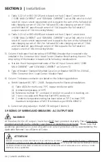
4) Column 3 indicates the size of external fuse in the battery circuit. It is
mandatory to install this fuse within 7” of the battery Positive terminal to
protect the internal DC Input Section of the unit and also to protect the
battery cables against short circuit. Amp rating of the fuse is based on the
following considerations:
SECTIOn 3 |
Installation

