48 | SAMLEX AMErICA INC.
SECTIOn 3 |
Installation
3.10 reSiDuAL Current DeViCe (rCD) ProteCtion For 230VAC MotorhoMe
/ CArAVAn APPLiCAtion
When this unit is installed in 230VAC motorhome / caravan, ensure that appropriate capac-
ity of residual Current Device (rCD) is used in the vehicle wiring system to protect all load
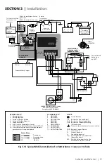
circuits. (refere to fig 3.14)
3.11 grounDing to eArth or to other DeSignAteD grounD
Grounding means connecting (bonding) to Earth Ground or to other designated Ground.
for example, in a motorhome / caravan / rV, the metal frame of the motorhome / caravan /
rV is normally designated as the Negative DC Ground. Similarly, all metal portions of boats /
marine craft are bonded together and called boat Ground.
Grounding is required for (i) protection against damage due to lightning strike and (ii)
protection against electric shock due to “Ground fault”. In case of EVO
TM
, “Ground fault”
may occur due to inadvertent contact between an energized ungrounded current carrying
conductor and exposed metal surface resulting in voltage getting fed to (i) the metal chassis
of the EVO
TM
or (ii) to the metal chassis of the devices connected to EVO
TM
or (iii) to the metal
frame/ chassis in a motorhome / caravan. When this energized exposed surface is touched,
the voltage will drive current through the body to Earth Ground producing electric shock.
When properly grounded to Earth Ground (or frame / Chassis Ground in motorhome or cara-
van), the Leakage Current Protection Device (like rCD, GfCI etc.) or Over Current Protection
Device (like Circuit breaker or fuse) will trip and interrupt the circuit feeding power from the
AC source (EVO
TM
/ Grid / Generator) or the DC source (12V / 24V battery). Proper grounding
will ensure that all exposed metal surfaces will have equal potential and will be bonded to (i)
a single common Earth Ground point i.e. the Ground rod / buried metallic water / gas pipe at
the premises or (ii) the frame / Chassis Ground in a motorhome / caravan.
Please read the following on-line white Papers for complete understanding of
grounding at www.samlexamerica.com (home > Support > white Papers):
“Grounding System and Lightning / Ground fault Protection”
3.12 grounDing ArrAngeMent in eVo
TM
SerieS
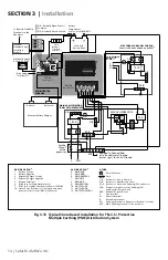
Schematic at fig 3.12 illustrates typical grounding arrangement of EVO
TM
Series for shore
based installations with TN-C-S / Protective Multiple Earthing (PME) Power Distribution Sys-
tem. Schematic at fig. 3.14 shows grounding arrangement in typical mobile installation.
Internally, EVO
TM
consists of AC and DC Sections isolated by a transformer (fig 3.12). both
these sections are required to be grounded appropriately.
3.13 grounDing - AC SeCtion
For typical Shore based installations using tn-C-S / PMe Distribution System
(Please see Fig. 3.12)
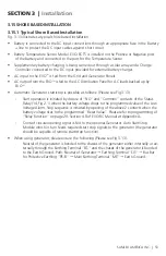
The bus bars for Protective Earth (PE) conductors “PE-b” located in (i) the Main AC Dis-
tribution Panel of the Premises (ii) the DC Distribution Panel and (iii) the AC Distribution
Panel for AC Loads backed Up by EVO
TM
are all electrically bonded to the “Main Earthing

