50 | SAMLEX AMErICA INC.
SECTIOn 3 |
Installation
EVO
TM
being used. The wire size used for DC side grounding should be minimum 10mm
2
or of
the same size as the battery cable, whichever is thicker (battery cable size should have mini-
mum Ampacity ≥ the Ampere rating of this battery fuse (150A to 400A) depending upon the
model of the EVO
TM
being used).
this recommendation on sizing of the DC Side ground-
ing wire will be superseded by the national / Local electrical Codes.
!
CAution!
As per American boat and Yacht Council (AbYC) Safety Standard E-11 for the AC and DC
Electrical Systems on boats, the size of DC side grounding wire shall not be smaller than one
size under that required for current carrying conductors supplying the device. Hence, for ap-
plication on EVO
TM
on boat / yacht, the size of the DC side grounding conductor should be of
the same or one size smaller than the size of battery cable specified in Table 3.1.
!
Attention!
Conformément « American Boat et Yacht Council » ( ABYC ) la norme de sécurité E - 11 , la taille du fil de mise a terre du côté
CC ne doit pas être inférieure à un format sous celle requise pour les conducteurs tenant le courant pour alimenter l'appareil.
Par conséquent, pour l’application EVO
TM
sur le bateau / yacht, la taille du conducteur de mise a terre côté CC devrait être de la
même ou strictement une taille plus petite que la taille du câble de batterie indiqué dans le tableau 3.1.
inFo
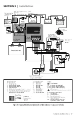
As described at Section 3.13, the metal frame / chassis of the EVO
TM
(fig 3.12, G1) is bonded to
the Main Earthing Terminal “ME” for AC side grounding. It may be argued that if the metal frame
/ chassis of EVO
TM
is already bonded to Main Earthing Terminal “ME” for AC side grounding, why
is it necessary to provide an additional DC side grounding wiring? (Wiring that bonds DC Ground-
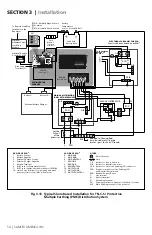
ing Terminals "GE", "PE-b" and "ME" in fig 3.1). If separate thicker grounding wire of the same
size as the battery cable was not provided for the DC side grounding and there was a ground fault
in the battery circuit, very large DC fault current from would flow through the smaller
size AC grounding wires to the battery Negative through the Main Earthing Terminal “ME”. These
smaller size AC side grounding wires would be damaged due to very high DC side fault current
(150A to 400A depending on the Model of the EVO
TM
being used).
DC Side grounding Arrangement for typical Shore based installations using Protective
Multiple earthing (PMe) or “tn-C-S” earthing System (Please refer to Fig. 3.12)
A DC Side Grounding Connector (G2) (5 in the DC side layout in fig. 2.1) is provided in the
EVO
TM
. This connector is internally bonded to the metal frame/chassis of the EVO
TM
. Con-
nect this DC Side Grounding Connector (G2) to the Negative (-) bus in the DC Distribution
Panel (In case DC Distribution Panel is not used, connect it directly to the battery Negative
Terminal). The wire size should be minimum 10mm
2
or of the same size as the battery cable,
whichever is thicker. battery cable size should have minimum Ampacity ≥ the Ampere rat-
ing of the battery fuse (150A to 400A) depending on the model of the EVO
TM
being used).
The Negative Terminal of the battery gets connected to the Earth Ground through the path:
battery Negative
"
Negative (-) bus in the DC Distribution Panel
"
bus bar for Equipment
Grounding Conductors (PE-b) in the DC Distribution Panel
"
Main Earthing Terminal “ME”


